| Send
items to chuck.leinweber@gmail.com
for inclusion here next month.
The Treasure Chest is a place to put those cool sailing,
cruising, motoring, boatbuilding or boating tips you have. Send
us your ideas...
This time we have...
Bevels
I use this technique to cut the bevels on bulkheads/frames. I setup my table saw with a pattern cutting jig, then tilt the blade to the desired degree of bevel. Adjust the jig so that the outside edge of the blade is even with the edge of the jig, just like you'd do if the blade was at 90. A test cut or two will be in order. All your framing should be cut just a little over the largest dimension, by an 1/8 inch let's say. Stick a cleat down on the desired cut line with some carpet tape, and make the cut on your table saw. I used this on my AF4 bulkheads which allowed me to glue the plywood onto the framing sticks a little oversized, then trim the excess plywood off (as well as that extra 1/8 of framing lumber) as the bevel was cut. It also eliminates the gap on "outy" bevels that Jim Michalak recommends filling with glue. Shopnotes has a good video of the technique in action on irregular shaped pieces, albeit without the blade tilted.
Joe
PDR Building Bench
I can't speak highly enough about the use of a bench we called it the Everything bench for the final assembly of PDRacer #373, for #374, and another hull that is not quite 3d.
This bench was 2' tall, but could be anything from 18-30", depending on builder height. The initial version was a leftover cabinet assembly bench, which morphed into a full 4x8.
The 4x8 top provides a clamping surface and also insures the hull will be square and flat.
Bob Cavenagh
Low profile through the hull drain plug installation instructions and photo’s.
Due to the air box location there is no transom on this boat. Draining through the hull is the only practical solution.. Therefore I decided to install a floor drain but I needed a low profile with little material added on either side of the hull. I also wanted a drain plug I could install with minimal work..
|
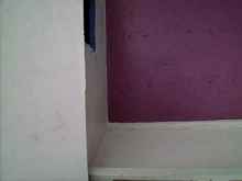
Selecting the location for a drain hole. I decided on the back starboard corner near air box right through the hull. |
Then I placed the drain washer inside to get an idea of the exact location for my drain. Next I marked where I wanted to drill…
Another note. In this photo you can see the sheet rock tape on the inside chines. Years from now with more painting the weave will almost disappear..
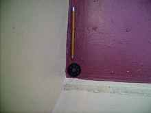
Drilling part way through hull from the inside, don’t want to damage the ply on the other side so I stopped short.
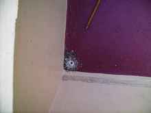
Next I drilled from the bottom of the boat making the hole the rest of they way through. This leaves a nice clean hole smooth on both sides. Sand paper the edges and seal the wood all away around inside the hole using Super Glue. I used the thin stuff and a plastic wall mart shopping bag over my finger to smear it all way around into the wood grain. It cures better if you blow on it too. The moisture in your breath that cleans your glasses also helps the glue set. In this photo the sheet rock tape can clearly be seen on the outside bottom corner of the boat....Nothing fancy, just works great.
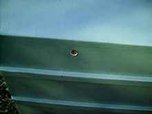
This is what the installed plug looks like viewed from the bottom of the boat laying on it’s port side. There’s not much plug showing on the bottom.. It’s a very low profile plug. The round part is the bolt head. Mine is hardened steel and can be dragged over concrete a few times if need be....I primed it with rustoleum, then top coat of latex to match the hull..
This is what it looks like from the inside with the plug in place and the wing nut tight. It’s tucked away in the corner out of the way.. I never put my foot in that spot anyway.. The plastic acorn nut keeps the wing nut from being lost when the boat is stored with drain left open. I applied a drop of Super Glue on the Acorn nut before it was installed. That keeps kids from taking it off but with the right tools you can remove it if need be.
The outside washer was greased with Petroleum jelly to keep it from bonding to my water base paint on the exterior of the hull.
The outside rubber washer is a 1.5 inches across. The alignment washer in the hole is .75 inches across. The drain hole is drilled with an 15/16ths bit. The big rubber washer has a lip all way around that is almost .25 inches. The rubber washer seals right to the hull..
Here is the drain open and ready for business.. The boat is stored in my barn with this corner left low.. If the barn roof leaks (again) I won’t find a boat full of water.. I have found water in the boat a few times after a big rain. Before the drain plug was installed of course. I repaired the old tin roof but who knows, it could leak again,, Now my boat will be safe leaky roof or not as long as I remember to open the drain plug..
Note. Don’t let the location of this drain fool you viewed from below. Looking at it from this angle it does not appear to be all way aft. There is a bulk head inside sealing the transom off from this point aft due to the air box so if you view the inside photo you will see this is the point where the water will drain to..
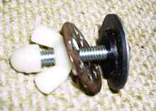
Detail of how to build the “Chiefredelk” Super drain plug.
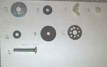
In this photo you can see the lip and shoulder of the water seal. This lip and shoulder is made up of two washers ( 4, 5 ) glued together. They are backed by #3 a metal washer. #6 is the washer with holes drilled to allow water to drain out. #6 goes inside the boat. In the photo it’s the part laying over against the wing nut.
This is the complete parts list and a description of the parts and what they do...
#1,a metal bolt long enough to go through the hull and hold all the parts together. ,#3,,#6 are big metal washers. Should be big enough to cover the hole with enough of an edge to seal the hole.
#2,soft rubber washer seals beneath head of bolt,,,#4 rubber washer seals drain hole, #5 rubber washer glues to #4 and fits loosely inside drain hole to align the drain plug
#7 Wing nut, holds unit tight to keep water out of boat. #8 Acorn nut, keeps wing nut from coming all way off. Covers end of bolt.
Here are more detailed instructions listing the 7 steps of assembly.
Every thing goes onto #1 long bolt with big flat head and are installed in the order in which they are numbered.
Step 1. Put #2 on #1.. it’s a soft rubber washer that seals the bolt head
Step 2. next #3 goes on #1 it’s a big metal washer. Should fit bolt properly. It’s a pressure washer
Step 3. next #4 goes upon #1 Rubber washer that fits against metal washer.# 3 and #4 should be the same size around. #4 is the water seal.
Step 4. now #5 goes upon # 1. #5 keeps the unit lined up in the hole. It should be super glued and centered upon #4. It’s the alignment washer.
That completes the outside part of the plug which is the part that goes through hull hole from outside
The parts that go inside are, parts, 6, 7,and 8
Step 5 #6 goes upon #1
Step 6 #7 goes on #1
Step 7 lastly #8 goes on the tip of #1
Notes..#3 and #4 should be the same size around and you can choose these sizes as long as they cover the drain hole enough to seal. #5 is ¾ inch diameter because it fits the drain hole I drilled. You can change that too if need be..#5 is glued to #4 to center the drain plug with the drain hole.
Drill hole to fit what ever size your #5 washer is. Mine is ¾ so it needed a 15/16th size hole..
Chief
Scarfing Jig
Boatbuilding requires dealing with long, floppy, sometimes heavy pieces of wood. While it may be possible to run these pieces of wood over stationary power tools, I do better to rest the stock on a solid surface and make my cuts with hand held power tools.
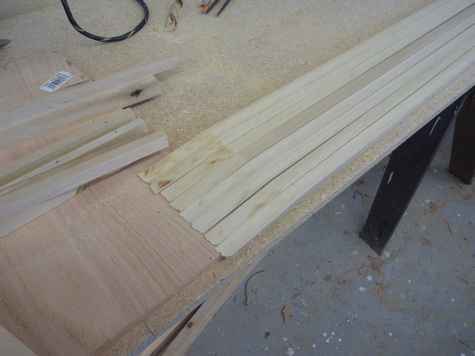
Generally, even small boats require pieces of wood for gunwales and keels which are longer than easily obtainable lumber. When this happens, it is necessary to scarf two or more pieces of wood together to obtain the necessary length. A scarf is made by cutting the ends of the wood at an angle and gluing the cut surfaces together. The length of the scarf should be about 8 times the width of the of the wood being scarfed. In this example, the wood is ½” thick and the scarf is 4” long. Cutting scarfs requires that the cuts be made with some precision and that the cuts on several pieces of wood be identical. I have seen write ups for a variety of methods involving routers, table saws, or miter saws. I’m sure they all work, but I prefer the following jig.
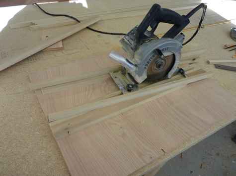
Two parallel pieces of wood are nailed to a piece of scrap plywood. The spacing should be a snug fit for the wood being scarfed. Two more parallel pieces of wood are nailed across the first two at the appropriate angle. The top two pieces act as a track for a hand held circular saw (known around here as a “skil saw”, though I prefer a Porter Cable).
In building this jig, there are a couple of things to watch out for.
1) Since you will be running the saw across the first two parallel pieces and the stock, the parallel pieces need to be the same thickness as the stock.
2) The saw track pieces need to be supported by material the same thickness as the stock.
3)You need to keep the nails away from the cut line!
4) Nails need to be driven flush.
4) Make a cut without any stock in place to make sure your saw depth is good.
5) It is necessary to support the stock along its length and I do this by placing another pieces of scrap plywood at the bottom of the jig.
Use of this jig is simple and quick. Place the stock in the jig and make a cut. Remove the stock and the cut off piece, insert another piece of stock, and repeat. I made the eight cuts shown in about 5 minutes. These cuts are ready to glue up as they come out of the jig and the resulting scarfs are pretty darn good.

This jig is simple to make, is accurate, quick, and safe to use. What more can you ask?
John and Kathy Trussell
Roller Furler
I have been lurking on the Duckworks boat builders form for some time now. Although I have never built a boat, I did come up with this roller furler, made from odds and ends found around the house and at thrift stores.
This is Danu. I bought her as a bare hull and had the dagger board well and mast partner built and installed by a professional. The mainsail and rudder blade came from Ebay, I built the tiller, which is a set of military surplus tent poles, and the rudder head.
The mizzen sail is from Duckworks, and in lighter winds she sports a larger balanced lug mainsail. I usually sail with both sails on board, and change out as needed. It was the addition of the lugsail that made me think about converting her to a yawl. She seems pretty well balanced with the small sail, but exhibited some lee helm with the lug, which sets further forward on the mast. I sail the full mizzen with the lug, and about half furled with the smaller sail.
The mast is the top half of a two piece windsurfer. The base of the mast is the female end of a 1 and a half inch fire hose. It screws on to the male end that is riveted and glued to a fuel filler tube from a bombardier snow cat (hidden from view under the seat planks). The boom is a pool cue. The cleats for the mizzen sheets are pop riveted to some aluminum brackets scavenged off of an old commercial ski rack and pinned to the oar sockets of the rear rowing station.
When you remove the rubber gasket from from the hose connection and add some lubricant, the mast rotates even though the threads are turned tight. The wood discs on the top and bottom of the furler are glued to the mast. The boom fits into a socket made for a chain link fence, pop riveted and glued to the piece of aluminum pipe that is the rotating segment of the furler. Uncleat the line from this segment and pull the sail out onto the boom. With two sheets and the blue line off the boom kin, the sail can be held in any position. The boom kin was made from the outside segments of a wooden crutch, bolted and glued together. It has almost the perfect curve for centering the mizzen, and no steam bending required.
When the desired amount of sail has been unfurled, pin the rotating segment, pull the furling line tight and cleat it off.
Blake Chartier
Red Lodge, Montana
How Do You Know If A Marine Audio System Is Waterproof?
Take A Look Inside
CAMPBELL, CALIFORNIA (USA) – Not all marine audio systems are created equal. Many of the popular brands of audio systems installed in boats are not manufactured to Ingress Protection (IP) ratings high enough to prevent damage from prolonged exposure to moisture, water spray, or dust.
In plain English - they aren’t waterproof, according to David Goldstein, product specialist for marine audio systems manufacturer Aquatic AV. “Waterproofing an audio system for marine use takes a lot of engineering and testing. Most manufacturers market their systems as marine, when all they really do is take their all-purpose system, paint it white and call it waterproof,” Goldstein said.
All it takes is a quick look inside to determine if a marine audio system is waterproof. After just one season, the component on the left, which had been advertised as marine grade but not manufactured to an IP waterproof rating, is already showing significant signs of corrosion, while the component on the right (manufactured by Aquatic AV to an IP rating of 66, good protection against ingress in the marine environment), shows no signs of damage.
IP testing is a worldwide certification that tests products for water and dust resistance. An IP rating has two numbers after the letters IP, for example, IP66. The first number is the amount and the pressure of dust that can be sprayed at a unit. The second number is the amount and pressure of water that can be sprayed at a unit.
An IP66 rating is a good rating for a waterproof audio component. It indicates that the component can withstand any dust sprayed at it and it is completely sealed. It also indicates that water can be sprayed at it at 14 PSI, which is a pressure sprayer spraying the unit up close with no loss of function. For more information about IP ratings, visit www.aquatext.com/tables/ip_ratings.htm.
“Multiple steps are required to manufacture an audio system to be waterproof for marine use,” David Goldstein said. “First, the circuit boards are coated with a special waterproof gel and placed into a stainless steel or rust proof chassis. The chassis is then sealed completely to keep all water or moisture out of the completed component. Next, the faceplate of the component is completely sealed - when closed, there are no holes for water to enter into the chassis.
“The faceplate is injected with silicon to leave less airspace for condensation to occur. In a waterproof unit all screws are stainless steel to prevent rusting and sealed with special glue so water cannot enter the unit. Once the unit is assembled, a marine grade connector is installed on the back for a watertight connection. Only then is the unit ready for testing and if it passes, then the manufacturer can legitimately claim it is waterproof for marine use,” Goldstein said.
For more information about Aquatic AV products, visit www.aquaticav.com or call 1+408.559.1668.
Thanks to all who contributed this month. We got great ideas sent from far and wide. Put your thinking caps on and come up with those ideas for next month. Mike John
|