My wife has been harassing me to sew some better sails for “her” schooner. I told her I needed to practice by sewing a bimini for (“my”) motorboat. Clever, eh?
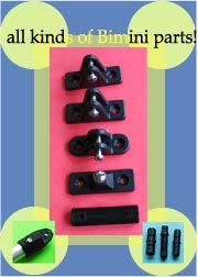
But it was a good idea anyway. If you’re as white as me, you really want a bimini to keep the sun off. Even in the milky Midwestern sun, we pasty people turn into boiled lobsters far too quickly. The time-honored answer is the bimini top. Fortunately, Duckworks has the best price to quality ratio around on bimini hardware, and also carries Sunbrella fabric.
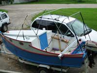
Unfortunately, a bimini on this particular boat is a rather tall order. It can’t interfere with the oars set up or struck, and when struck it needs to stay out of the way of starting the motor and walking forward through the slot top. This basically means it has to collapse inside the cockpit aft. The trouble with that is that the cockpit on an AF4B is only five feet long. This presents problems.
Drawings
Do yourself a big favor and make drawings in scale when figuring out things like this. The only other way to get it right is clamping tubing to the boat and standing back to look at it. You can make drawings on days when you’d rather not be outside clamping things.
Below is a drawing of the general layout. This has 6 feet of headroom in the middle and 5’9” at front and rear of the bimini. (The middle always has to be higher to keep the fabric under tension.) The dotted line is where the frames would lay when tilted forward during setup. When tilted aft they’re way out over the motor.
 click images for larger views click images for larger views
At first it seems like the uprights will fit – they’re only 4’10” long. But this is only true if you use sliding hinges on the middle bow – otherwise it’s longer than the others! But even with sliding hinges and 4’10”, it doesn’t really fit. We’d need the lower hinges on tracks that could get from the far forward corner of the cockpit to our anchor point. Thirty inches of track per side seems extreme.
This version is centered right over the cockpit, no overlap fore or aft. If you had wheel steering you might want to sacrifice coverage at the rear to make it overlap the front of the cockpit to keep the sun out of your eyes. With tiller steering you’re out of luck – any further aft and the aft tie-down will be making too acute an angle with the frame. You’d have to make the whole thing lower. I have stick steering so it should be fine as drawn.
Or I could cut the uprights a little shorter and move the hinges forward a bit. So let’s try moving it forward 6”.
Well, retraction is not much improved. We could probably gang together the aluminum slides end-to-end to get the 24” we need. But these kind of extreme measures make me think I’m barking up the wrong tree. The short cockpit makes AF4B a good boat for exploring alternate support methods.
To be fair, the higher freeboard on an unmodified AF4B would require uprights about 4” shorter, which would make this a little easier.
Removable Frame
In this case it seemed easier to avoid the retraction problem entirely and make the bimini easily removable so it would break down and bundle up for storage. This also makes it easy to bring it indoors when the boat is out of use for a while – by far the best thing for its longevity. This also means we don’t need to bother sewing a storage cover.
Duckworks has tube connectors to make this easy. So we build the frame just like we normally would, then cut it where it’s convenient and install connectors. The fabric will live on its bows, and the uprights will detach. Then the whole thing bundles together for storage.
Here’s the really cool part of this removable approach. It can also support the cover tarp by using shorter bows. With hull drains, keeping the water out isn’t the biggest deal, but if you don’t keep the leaves out, the drains will plug in short order.
OK, let’s get to building this thing.
Frame – First Attempt
From our drawing we know how tall we want the bows to be. Let’s start with the bow that actually attaches to the boat. Lee Martin shows us the bending technique in his article posted last year. The biggest advantage of Lee’s technique is that it is easy to plot out where the outside part of the angle will end up, so you get a bow of the right width. This is trickier with a tubing bender unless you practice a bit.
Here’s my Martin bending jig screwed to the deck. The square was used to mark the 90 degree angle the bow should bend to.
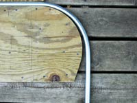
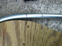
Just like Lee said, I used a piece of 1.5” PVC pipe as a cheater bar. But here’s an important consideration. There is springback, so the tubing does not end up at the theoretical 90 degree line. Instead it ends up approximately an inch outside that line. I didn’t bother to measure how far. I just marked where it ended up so I could measure from that line when doing the other end. Making one bends in each of three bows showed me that this springback line was repeatable. (You can see the theoretical 90-degree line cut into the deck with a knife, but the springback line is in the shadow of the tubing.)
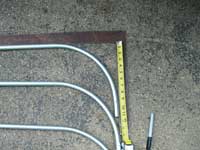
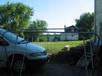
Now we have three half-bows, so we need to know how wide they will need to be. I mounted the hardware on the boat and put in two of the bows so they overlapped. This was only so I could measure the width from the outside of the tubing on one side to the outside of the tubing on the other side.
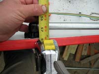
For my installation, I need 57” bows. So back at the bending jig I lay down the tape measure with 57” lined up on the springback line.
Then the already-bent end of the bow gets lined up with the end of the tape. This ended up being off the edge of my small deck.
Then we make the next bend. To get both “legs” in line with my setup, the already-bent end needed to be slightly elevated, since it’s impossible to bend completely flat against the deck. This may seem like quite an odyssey, but really I only had about two hours in at this point, including making the bending jig.
Notice the untrimmed bows. Don’t try to get the upright parts to the correct length until after you bend it! It is quite difficult to make a bend where the end comes out right where you want it to. It is much easier to cut to length after the bending.
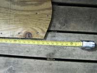
To decide where to cut, I made marks on the same jig. I guess I could have saved time by doing this while bending. The two marks represent the edge of the cloth and the cut. I wanted a couple inches of extra tubing so it wouldn’t get lost in its fabric pocket so easily.
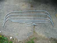
And here they are cut to length.
Now we need the uprights. These dimensions can be read (in scale) directly off the drawing. In my case, I need 58” main uprights and 32” secondary uprights. But the bows take up some of that distance. How much?
Taking 11.5” off each of those figures, I need two lengths of 46” and two lengths of 20.5”. Notice that I’m still two pieces short. This is because the other long pair needs to be a touch shorter, as it attaches to fittings on the 46.5” set. Now we need fittings. The drawing tells us that one fitting goes 27” from the bottom and the other is almost right at the bottom. The lower one might have to go a bit higher than you planned to avoid running into the hull or interfering with the screw on the bottom plug. In any case, once you have all that figured out, cut the final pair of uprights so they come out to the same length as the main uprights when folded. (Unless of course your design drawing indicates differently.)
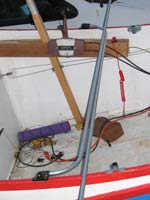
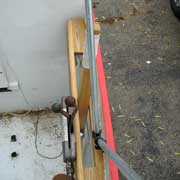
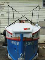
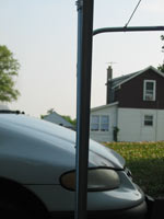
Plug-type hardware is so loose in EMT that it falls right out. I crimped it in place by punching some dimples with a centerpunch. (This ended up not working so well, but we’ll get to that later.) Time for a test fit.
Houston, we have a problem.
After inventing a few new curse words and revisiting a few favorites, I decided that this was fate intervening to make this a more interesting article. Yeah. That was it. Notice how I made profile drawings above, but neglected the section view? This was a bad idea. But it might not have helped anyway, because I designed the bimini frame before adding the stick steering system. But at least I could have looked at the drawing and thought, “Where’s the stick?”
Back to the Drawing Board
Well, I had to make new bows no matter how you slice it, since these were too narrow. Good thing I used cheap steel EMT! Let’s look at hardware options.
My hardware choice was actually doubly inappropriate, now that I think of it. The bracket is a side-mount on the inside—that’s one offset toward the stick. Then the end plug that mates with it is also a side mount—so a second offset toward the stick. Unfortunately, my stick design will not tolerate any offset without interference.
So what we really want it a top-mount snap on bracket with an end-mount snap in plug. Unfortunately, this option does not appear to exist! But I guess I only have to take out two screws if I give up the snap-on operation. Better yet, I can use an angled bracket, which eliminates the slight binding with the current 90-degree snap-on hardware.
But as it turns out I don’t have to mess with two screws anyhow! The clever Chuck Leinweber suggested I simply cut a slot in the end cap so it could slip onto the permanently-mounted screw. The retaining straps for the bimini would keep them in place anyway. Brilliant!
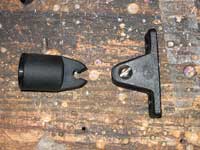
These plastic fittings cut easily with a wire cutter, and if you’re careful you can even get snap-on operation. Hardware invented and crisis averted. (By the way, can you imagine getting that kind of innovative service from a big supplier with a phone center somewhere in Asia? I didn’t think so.)
Bending Again
I decided to completely start over using a tubing bender so we can see how it works with one of those. The trouble with these tools is that it’s hard to know exactly where your 90-degree leg will end up. There are markings on the tool that are supposed to tell you how to do this, but they are not always easy to figure out. The numbers on my bender were clearly meant for a different task, so I derived my own number.
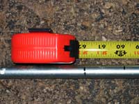
All of these benders have a pointer near the “saddle”, and all references are from that point. You can learn all you need to know on the first bend. Here’s the bender lined up with a mark. There’s another mark 10” away.
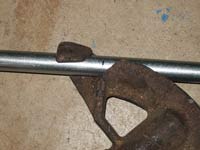
Most of these benders will go a little past 90 degrees, and it’s very hard to unbend tubing. Don’t go too far! You need to make these bends with the tubing against the floor anyhow, so just finish the bend with a carpenter’s square standing up next to the tubing. Finish the bend in small increments so you can see when the springback lines up with the square, viewed end-on.
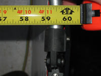
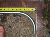
After bending to 90 degrees, the same square tells us how far from the mark the outside of the bent “leg” lands. The “other” mark is now 7.75” from the corner. So the offset is 2.25”.
This seems a little odd, so I try another one. I must have slipped on the first one, because the real offset for this bender is 2”. So for any bend I mark 2” outside where I want the corner, and put the bender saddle out with the pointer on that mark. Write this figure down and keep it with the bender so you don’t need to figure it out again next time.
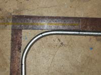
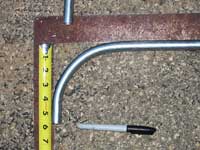
After making the first bends in each bow, we need only mark each bow 2” outside where we want the upright to be, put the bender’s mark on the mark, saddle pointing outward, and bend it. Easy! Here you see the two marks 10” apart, plus the bending mark another 2” out. You can also see how the angle ends up at 10” on the square.
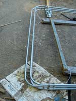
So let’s figure out the width we need. Again we bind together two half-bent bows.
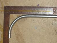
So if we want a bow 59-7/8” wide, we mark it at 61-7/8”. It is easiest to get this measurement by lining up the already-bent end with the square.
Then mark from the tape.
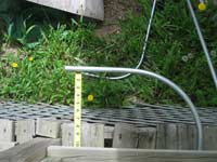
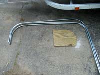
Then we apply the bender. Repeat twice and we have our bows. Notice how these have a much smaller radius than the ones I made with the wooden jig method. This might be an advantage, as the resulting bundle won’t be as bulky and it will be easier to see out from under the bimini when standing. I marked the cutoff points 5.5” from the top using the same carpenter’s square method.
Since we know the bows now take up 5.5” of height, we can cut our main pair of uprights to 52.5”. The hardware gets installed as before, and the second-longest uprights are cut to match. The shortest uprights needs to come out 2-2.5” longer than the others (dimension not critical since we haven’t made the canvas yet). So again it is easiest to mount them in their hardware and then cut to length. Everything fits this time.
Notice how I used lines to keep the bows in place? We don’t have canvas yet, so again some Dacron line or wire will keep the bows 30” apart as designed.
Floppiness
Something isn’t quite right, though. The frame is quite rickety side-to side. Crossing the front straps made it much stiffer.
In this setup, the front bow is very stiff and the rear is still floppy. But the shape became unmanageable if I crossed both front and rear straps. Something isn’t quite right here, since diagonal bracing shouldn’t really be required. Even when I moved the straps down to where they normally go (90-degree angle to the upright), the problem persisted. I traced the looseness to the connectors that join the bows to the uprights. These are located near the corners, where we need maximum stiffness to make up for the play inherent in the lower hinge assemblies.
The trouble here is that these connectors are designed for aluminum tubing and I’m using cheap steel EMT, so the fit is too loose. My dimple method keeps the connectors from falling out, but doesn’t make them stiff. I tried adding electrical tape and PL400 to snug up the connections, but neither helped noticeably. (The end cap fittings seem fine, as they are held in place with setscrews, and they are at a less sensitive location.)
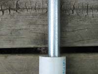
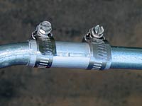
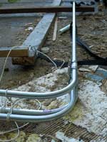
If you’re using EMT, I would skip the butt connectors and make sleeves instead. I used 2.5” chunks of 7/8” aluminum tubing I had in the junk bin. I slit the tubing so it could fit closely and put them together with hose clamps.
My bows were too short to accommodate both clamps and still have room for the canvas, so I tried JBWeld and solder in place of the upper clamp. Solder won’t stick well and JBWeld will crack. So I got to make yet another set of bows! I think I did that last one in my sleep, because I don’t really remember it. On the upside, this bender business is getting pretty easy by now. This time I made the “legs” 8” long and trimmed 2.5” off the uprights. Finally we’re back to setting up yet again.
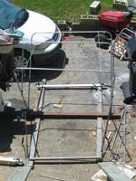
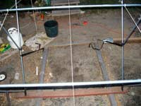
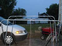
You will be taking fabric back and forth to the frame a lot for fitting. It makes life easier to build a base and erect the bimini frame on the floor. This eliminates a lot of climbing around and more than a few precarious moments perched on a gunwale.
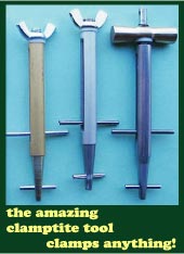
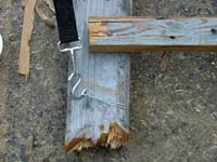
Note how the Clamp-Tite tool came in handy when I ran short on screweyes.
Geometry
The floor frame also makes it a lot easier to check your geometry. This first setup is the pattern for sewing, so we want to get it right. It seems like you couldn’t be far off if the bows are parallel and the distances apart are fixed, but it is indeed possible to mess it up.
So how on earth did this happen? They are parallel when laying flat.
And when set up, the uprights are all in line.
I made diagonal measurements on each bow down to the bottom connectors, and both sides were equal. But I knew they were equal because I cut the tubing correctly. I re-measured the 30” spacing of the tops of the bows. Good there too.
Got it figured out yet?
Then I measured diagonals between bows. There was the problem. My strap tensions were uneven, pulling one side of the frame forward. I could see it from the front top. In the photo below, notice how the bottom frame 2x4 (reddish) is not parallel to the front bow? It is hard to see, but if you follow the shadow of the front bow, it almost touches the 2x4 at the right side, but is maybe 1.5” away on the left. What should have looked like rectangles from above looked like parallelograms. Diagonal measurements can always expose this kind of distortion.
But how could this cause conflicting angles in the bows? Well, if one side is rotated forward, the front bow will be rotating downward and the rear bow will be rotating upward. The other ends of the bows stay the same, so the slopes of the front and rear distort in the opposite direction. This is actually good, because parallel top bows tell us we’re pretty well aligned. And it’s an easy adjustment once you understand it.
An extra 15 minutes of measuring and adjustment improved the final shape a great deal. Give this a final check before starting on fabric. But first let’s add some lines.
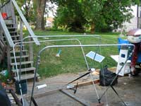
You already saw the mason’s twine in the middle, marking the centerline. This lets us get an end view of alignment and will come in very handy when we get to the canvas. By the way, I figured out where to tie the ends of the center line down by measuring diagonally from the bottom fittings on the main 2x4. Any point equidistant from those two fittings is on the centerline.
I also added twine to mark the hem lines. I made them 5” down from the bow top at the ends and 6” down on the middle bow. This is mostly a matter of taste, as long as you get it low enough that the frame tension holds the canvas in place, and high enough that you can see under it when piloting the boat.
Well, this probably should have been a short article but for all the mistakes I made. But I think this is a good thing. Now you don’t need to make them. Next time we’ll look at how to use these lines for marking and sew some canvas.
Rob Rohde-Szudy
Madison, Wisconsin, USA
robrohdeszudy@yahoo.com
On to Part 2: Canvassing |