"Can a Few Simple Modifications Make a Clever, Proven DIY Roller Furler Design Even Better?"
Kirk Gresham described his innovative design for a DIY roller furler in Small Craft Advisor in #58. It caught the eye of a lot of sailors, including another creative gentleman named Joel (last name unknown) who built a Welsford Navigator. Joel made some really clever, additional improvements to the design. The result is the most accessible (i. e., buildable), coolest DIY furler design of this quality that I have seen. Joel has kindly posted instructions for building the design and attests to its practical effectiveness here. Importantly, the design can be built for under $40, which includes the swivel needed at the top of the mast.
I needed a trio of roller furlers for an experimental rig I'm using on a little trimaran I built this past summer. I liked the Gresham/Joel design a lot. But, I needed slightly more volume on the spool to hold more roller furling line. I also had a few thoughts on how to make the furler easier to build and perhaps a little stronger and more durable. So, I ended up building a trio of Gresham/Joel furlers with modifications shown here. The modifications might be of interest for a few reasons:
o The modifications enable really fast construction with almost nothing to fabricate because all parts are bought pre - made from Home Depot or similar. Except for drilling the PVC cover, there really is nothing to fabricate. It is possible that you might have to drill your top flange (see below) to fit a u-bolt, although I was able to find a u-bolt that fit the manufacturer's pre-drilled flange holes.
o All the parts are inexpensive, keeping the same low price.
o The spool is built from a pair of galvanized pipe flanges and a ½ x 2 inch coupling. Easy. The all-metal construction is strong and durable. I'll use this in fresh water where the galvanzied parts should have a good service life. I expect the PVC cover to be the first part to go, as PVC can get brittle in the sun. I may paint the PVC.
o The assembly drawings (below) show that the bottom of the spool is fully supported on the inside of the PVC cover to help stabilize the spool AND the shaft on which the spool is mounted. This helps reduce the risk that the shaft will bend or suffer similar damage. The spool is an annular brace for the shaft.
o The spool has double the volume for holding roughly 12 to 14 feet of furling line without making the overall package any bigger. This is more than enough for the sails I'll have on my little trimaran.
o The furler has great spinning action. I have not experienced a jam yet. Like the original designs, it will be easy to 1 service and repair as needed.
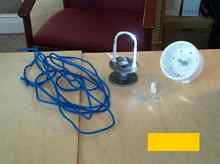
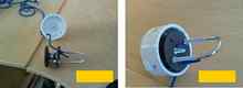
First, I'll show the assembly in photos. Then I'll show the assembly in a series of schematic drawings. Fig. 1 shows almost all the parts you need. You see the spool assembly made from two ½ inch pipe flanges, a ½ inch x 2 inch threaded pipe coupling or nipple, a 5/16 U-bolt have an arm spacing that fits the pre-drilled holes in the top pipe flange, a PVC cover drilled with holes on the side and through the bottom, a 5/16 inch eyebolt bolted to the PVC cover to serve as a spool shaft, a furling line, a short length of 3/8 PEX tubing to serve as an adapter between the eyebolt shaft and the spool, a regular washer, a nylon washer, and a furling line. Not shown is the 5/16 nylon lock nut you need to secure the spool on the shaft. Also not shown is the glue used to "lock" the threads on the spool. I used superglue on the spool (but nylon locknuts elsewhere without glue to allow disassembly later for service) because it cures fast and is waterproof.
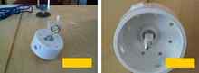
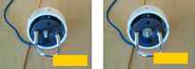
Figs. 2a and 2b show top and bottom perspective views of the eyebolt shaft fitted to the PVC cover. The 5/16 shaft of the eyebolt is the thickest eyebolt whose washers and nuts will fit inside the spool. This is important so that the spool is supported directly on the PVC cover. The PVC cover is slippery and makes a good bearing surface for the spool assembly. If sand were to get in, this might cause binding and should be washed out. I haven't had this happen. In Fig. 2b, the short length of PEX tubing/adapter is already fitted onto the shaft. Joel, mentioned above, innovated the use of the PVC cover as a drum body. This is off the charts clever and effective. The drum body does a great job of holding and guiding the furling line.
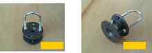
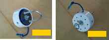
Fig 3a and 3b show the spool assembly. This is easy to make. Simply attach a pipe flange to each end of the pipe coupling. Use a thread fixative to keep the flanges from coming off. I used superglue. Then, secure the U-bolt to the top flange. The arm spacing on my U-bolt was the tiniest bit too narrow to fit into the pre-drilled flange. I got it in with a little coaxing. Here and everywhere I used nylon locknuts for security. I did not use fixative with the nylon locknuts so that I could disassemble for service and upgrades.
Yes, the spool is a little skewed because the threads on the coupling are off. This does not affect furling action.
Let's put this all together. In Fig. 4a the furling line is threaded through the spool and PVC cover. In Fig. 4b, the spool is mounted onto the shaft in the PVC cover. You'll notice that there is a gap between the spool flange and the PVC cover that is large enough for the furling line to "leak" through. I have not seen this happen, and the gap seems to prevent jamming that I observed with narrower gaps. It only takes a tiny bit of line in a tiny gap to cause jamming.
In Fig. 5, add the regular washer on the shaft and center on the spool assembly. In Fig. 6, add the nylon washer and center on the shaft. Then, in Fig. 7a add the nylon lock nut and tighten. It should be tight enough to remove as much slack as possible, but loose enough that the spool spins freely. The furler is done! Fig. 7b shows a bottom view of the finished furler. In Fig. 7a, it looks like maybe some line is coming out the gap, but that is the stop knot of the line entering through the top of the spool. Joel's website (link provided above) explains how to use a furler like this. Schematic drawings showing more details are shown further below.
|