 Custom Search
|
|
| sails |
| plans |
| epoxy |
| rope/line |
| hardware |
| canoe/Kayak |
| sailmaking |
| materials |
| models |
| media |
| tools |
| gear |
 |
 |
| join |
| home |
| indexes |
| classifieds |
| calendar |
| archives |
| about |
| links |
| Join Duckworks Get free newsletter Comment on articles CLICK HERE |
|
|
| Out There |
by Paul Austin - Dallas, Texas - USA Classic Ship Construction Notes - Part One |
 |
Part One - Part Two - Part Three - Part Four - Part Five- Part Six When a museum or non-profit organization looks into building a replica of a historic ship, they want to create a living testimony to the original men and ships that sailed the seas. Fortunately, we have dimensions and specifications on these ships to make a new ship authentic. The skills can be learned again, the wood is available, the designs can be used again, provided the spirit of the ship is alive. So let's look at some of the information about classic tall ships which shipwrights and volunteers would need to know. Maybe we can be a resource for a revival of interest in our own maritime heritage.
MODELModels from which to build a great ship have been used since prehistoric times. I once saw a picture of Nathaniel Herreshoff in a skiff near a dock, dropping down one of his models into the water, sails and all. He had a string attached to the bow. Model making once was a high art. Some men in the 19th century made a part-time living as model makers. Models in the age of sail were usually 1/4 inch for 1 foot, so they could be 3 to 4 feet long. Built up in layers, they could be complicated and ornate. The model would be scrutinized by the ship owner, the master ship builder, and the captain if he were a shareholder in the ship's future. They'd run their fingers over the layers, imagining the hold, the ship's speed, the sailing qualities they needed, and the depth of keel. The model might be worked on several times to satisfy all the parties involved for sail area, number of crew and their accommodations and deck space. The more accurate the model, the more time saved in lofting, mold making and fairing.
Models for naval ships could be as much as 6 feet long. From them would be generated the lines of the ship, the arrangement of the lines, the gun deck layout, the gunpowder hold, where the crew would sleep and eat, even where the cattle or sheep would be kept. Since navies took lines off ships often, the lines of a new ship could be compared to a previous one. The admiral might say, 'Our own Great Duck of the Sea, at 100 guns is not fast enough. Make this one just like it, but faster.' So lines would be adjusted without compromising the gun decks, crew size, or sail area. But with commercial ships, the lines might not be used. In this case, previous ships would have ratio specifications. This might be something like, 4 inches of beam for every 1 foot of waterline, or 1/4 inch of keel width for every 1 foot of waterline. Usually these specifications were in a small book owned by the owner, ship's captain or construction master. In the Scandinavian countries, these ratios were etched into wood tablets. After the model is done to everyone's satisfaction, the construction master would take his perfected model to the loftsman, who would scale up his frames, keel, stem, etc right off the model. Nathaniel Herreshoff invented his own device for taking lines directly off the model for the loftsman and draftsmen who would then fair them if they needed it. The master builder would then make sure the lines were faired, once again, as the ship is built. In the Old School ship design there are no mistakes, just lines to be adjusted. WOOD AND KEELWe can begin with the woods which were used in previous centuries. We would expect oak to be used for the keel, but red beech and elm were also used. The author Karl Marquardt mentions that oak splits upon hitting rocky grounds whereas beech only leaks Many English ships in the 17th century had elm rather than oak. The lower timbers, floors and first futtocks were also of oak. However, hackmatack would be the preferred wood for upper timbers. Hackmatack is lighter than oak and resistant to rot. The keel is the thickest, heaviest single piece of wood on the ship. The dimensions of the keel for ships of 50 to 100 feet are around 1/100 of the length of the ship - a 100 foot ship has a keel height of 1 foot, while its width is just about 10 inches. This slightly taller than wider keel gives it some stiffness against being bent up and down, with some flexibility side to side. This gives the keel solidness in the water against ocean waves while some flexibility when frames are laid athwartship and faired. As I write this, one foot doesn't seem to be tall enough for a 100 foot ship but when an outer keel and counter keel is added, the strength will be there. The master constructor will choose a man to find trees with a certain pattern of grain. The tree would be brought to the construction sight while it was still green, to lay outside over a season to stiffen and dry. Later, in the 19th century keels were taller for their width, up to 1 1/2 times their width. Evidently the more framing being put inside. the stronger the keel needs to be. In the great age of sail, property by the water was prepared for shipbuilding. Keel blocks would be sunk into the ground in two rows heading for the water. These blocks would be wedged or shimmed to create a slight decline toward the water for the ship to glide down after it is built. While the ship is being built, shims are put under the keel to make it level; then the shims are knocked out when the ship is ready to slide down to the water. Today, classic wood ships are built indoors on supports adjusted to the design of the keel. If the keel is lever to the waterline, no wedging is necessary but if the keel angles down the keel supports would be adjusted for that. We use cranes to bring a ship to the 'ways,' from which the ship is christened and slid down to the sea. These great ships were the most complicated structures in wood ever built. The knowledge gained and put into their construction is a study in itself. Great wood ships are huge, heavy and yet beautiful.
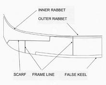
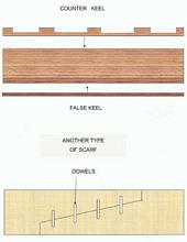
What really makes a keel are the scarfs. They're necessary since shipyards have realized that a section of keel over 26 feet does not hold shape. When the ship is 100 feet long or more, wood will squeeze itself out of shape as the moisture inside the wood moves around. Scarfs use that movement of moisture to press the 26 foot sections into alignment. Scarfs which are complicated in order to be strong give moisture more opportunities to ruin the voyage; scarfs which are too simple won't always hold up. The scarf will have to hold itself together, as there are no adjacent members to keep it in line. Bolts have been used to keep scarfs tight but they eventually will rust. And then when rabbets are cut into the keel near the top, this weakens the scarf somewhat. As a result, shipbuilders have developed scarfs which have worked over time. Any cut through the wood needs a hook to stay in line so that the next plank shoves itself against the previous one. But a hook is not enough. A scarf with only a hook would press the wood sideways, out of alignment. So builders have put wood dowels into the inside of the planks or cutouts called coaks to ingeniously fit one another. After the keel is scarfed together, false keels (sometimes called a shoe) are put on the bottom of the keel, running across the scarf joint. In earlier times a wedge was put underneath the keel but on top of the keel posts the same thickness as the false keel. Then after the keel was faired, it was raised a section at a time for the false keel to be put on in short sections in place of the keel posts which were knocked out. Sometimes a long plank called a counter keel is put on top of the keel. The counter keel has athwartship cuts in right angle notches for the frames, which stiffen the original keel considerably. Keels can't always be glued today, because they need to move ever so slightly with the moisture to keep from cracking. Usually a blacksmith was on hand every day to forge long true bolts for the keel, scarfs and the stem and stern joints.
The designer will have to put the scarfs where the scarf ends do not sit below the middle of any frame. This is quite critical at the bow's forefoot where different sections of wood come together. The frame lines would be marked with a sharp knife, then marked again with a colored pencil. These lines would be the center of the frames. The man marking them had to know if the ship had double-frames, whether the double frames had a spacer between them to ventilate the frame, or single frames as some warships. He had to know the frame width in single frames or where the double frames would land on the counter keel. As you can see, shipbuilding like this has to do with anticipating the next step in the building process. It took a certain kind of mind to hold on to 3 or 4 things for any one job - what had to come first and what would come later as a result of what you're doing.
Scarfs can be too long; they bend too much. On the big ships of the line, the scarf might be at least five feet long. On the European continent the scarfs were four times as long as the keel thickness, in the UK they might be longer for a warship. The longer the scarf, the longer the joining members can be for strength but the more give there will be. Shorter scarfs are stiffer but cutting exact shapes becomes a fine and critical job. Usually great wood ships had one type of scarf if the keel was one kind of tree, but they could have different styles of scarfs if the ship were large enough.
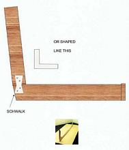
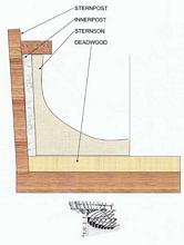
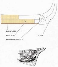
Where the keel enters the stern, the angle is usually strengthened with a metal strap or a squared-shaped piece of metal called a schwalk. Don't ask me why it's called this, it just is. Mention this at your next cocktail party - 'My dear, I like the way you schwalk.' See how you like the sidewalk with your hat in your hand. Inside the keel-sternpost connection any number of strengthening lengths of wood have been designed and used. The three main sections of wood are the keel, sternpost and deadwood. This part of the ship can be simple or complicated, usually depending on how much weight it will have to support. In 18th century ships, the captain's cabin was overhead, so the sternpost had to support the rudder and its hardware plus the stern sections with their multiple framing, notches and painting.
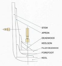
Now the stem has fewer pieces, and they are smaller. This is odd because the bow needs strength more than the stern. Designers have always known the bow takes a pounding in heavy weather due to its curved shape. The bow needs a rising rocker to stay above the sea, with flaring sections coming off the thick stem to shove the sea aside. And yet the stem is the weakest part of the ship. So in wooden ships, the frames as they approach the stem come closer together, they are turned slightly and gradually as they come toward the stem. These frames have to bend the most in the smallest distance, so their thickness can vary. The keel comes to the stem where it either curves or creates an angle. The forces at sea on this area of the stem-keel section are powerful. Curving the stem creates slightly less strain on the planks which come to the stem, but the stem which arrives at the keel at a sharper angle is a bit stronger.
Different designers made the stem-keel connection simpler or more complicated. The better designs rely on joinery rather than metal fasteners. When wood shoves wood it gives and returns to its shape, but when a ship is at sea a cracked keel will give you a bath in your bunk.
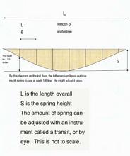
The scarfing done at the stem is usually the same as in the keel. In British ships the stem was slightly thicker than the keel, possibly to take more of the force of the sea. How far forward the stem protrudes from the keel was a designer's touch. The stem on 35-50 footers leaned forward 1/8 of the length of the keel, but on larger ships it would by less than half that amount. Some designers would create a rabbet that rose well up the stem, to extend the connection between the keel and stem. This was called boxing. And finally, the keel is going to 'hog' when it is in the sea. With the ends dropping as much as a foot, the keel is prepared for this by being 'sprung.' This means the ends are raised as much as 6 inches with the center kept down. Here is a layout of a spring guide.
*****
|