| A compilation of information
and tips from Rick Young, Steve Dashew, George Walner, and Bob
Gayle
Batteries - Depth of Discharge (DoD)
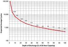 |
Figure 1 |
The relation between the cycle life of a battery and its DoD
is logarithmic as shown in Figure 1. In other words, the number
of cycles yielded by a battery goes up exponentially, the lower
the DoD. This holds for most cell chemistries, (eg. flooded, AGM,
and gel).
There are lessons here both for designers and users. By restricting
the DoD, the designer can improve the cycle life of the battery.
For example, look at the difference between 50% and 30% DoD -
the life cycle almost doubles. The important point to understand
here is that you can get longer life out of your bank of batteries
by either having more than the minimal daily capacity required,
or by topping the battery up before it becomes completely discharged.
The down side of installing greater battery capacity is the weight
and space they require, so typically a compromise is necessary.
Most people that write about this subject will tell you that a
cruiser should not allow their batteries to drop below a 50% DoD
because the life expectancy will diminish rapidly, which is true.
They'll also tell you that you shouldn't charge beyond 80%, because
the cost of charging is greater, (actually it takes longer), and
thus will offer diminishing returns and that as it turns out is
less true.
How to Kill Your Batteries
"In the industry it is estimated that about 85% of lead-acid
batteries die prematurely by being under charged. For example,
if you fail to reach a proper minimum acceptance voltage for a
sufficiently long period of time the battery continually degrades
and looses capacity on repetitive cycles. This is true for flooded-cell,
AGM, and gel cells; that are killed by permanent sulphation due
to undercharging, and includes standing for long periods short
of a full charge." "Most cruising boats are short of
a full charge, typically only charging to 80%, and most cruisers
have little knowledge of proper care for their batteries. I suspect
that the number for cruisers killing their batteries exceeds 85%
under repetitive undercharged cycling." - Rick Young
There is a simple reason most cruisers stop charging when the
batteries at 80% capacity. Most charging is done with the propulsion
engine's alternator, a separate generator or shore power, supplemented
by wind or solar. Since marina space is more expensive than fuel
most cruisers anchor out and use one or more of the other alternatives
to generate power. The ability of a battery bank to accept current
varies depending on its state of charge, after 80% a battery's
ability to accept current (amperage) decreases and slows down
dramatically; so getting that last 20% of charge takes hours,
which if you're using an engine or generator becomes a noisy,
expensive and inefficient use of fuel.
Battery Monitoring
A good battery monitor is the cornerstone of a good charging
system; it will measure kW-hours in addition to Amp-hours consumed
and returned. This makes monitoring the battery bank and maintaining
proper charge much easier.
Ideally you would perform a live test operating as you might
over a 24 hr discharge time and measure exactly how much energy
is used, but an estimate can be used to roughly determine the
size the battery bank and determine the space to accommodate it
and determine hwo the weight will effect trim. Knowing the kW-hour
number one can then decide whether or not to go with flooded,
AGM or Gel-cell batteries (Amp-hour numbers will not tell you
that because the three types of batteries having all the same
Amp-hour rating, will not have the same kW-hour rating). Those
cruisers using non flooded-cell constructed batteries, where you
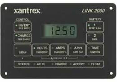
are not able to replenish lost water require
a monitor such as the Link 10 or Link 1000 for the longevity of
the batteries. A real battery monitor is one that not only shows
the usual Amp-hour status but actually measures true energy into
and out of a battery bank (kW hours) and one whose measurements
are stable for long periods of time and over a wide temperature
range. It should be capable of displaying battery status in a
simple, easily understood way that itself doesn't drain the battery
bank. Dollar for dollar the best real battery monitor is the Link
10 or the Link 1000 ($250). They display battery status using
LEDs. The LEDs are in a row of green followed by yellow and finally
red LEDs that act like a "gas gauge" for your batteries.
The milliamp load of the LEDs is far less than a digital or analog
meter, though a digital meter is integral to the monitor, switch
selectable for different displays, but remains off until desired.
The Link 10 has an optional battery temperature sensor (otherwise
you enter the ambient temperature manually). The Link 1000 is
temperature sensor "ready" yet I do not know if Xantrex
is making the temperature sensor for both of these products, since
it wasn't originally designed by them.
The Amp-Hour Law and 3–Stage Charging
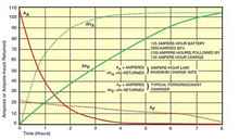
| Figure 2. The Current Acceptance and Charge
State of the Amp-hour Law 2 Also graphed is the 8 hour charge
cycle for a Ferroresonant (AC)Charger |
 |
"As good as Nigel Calder is he is wrong regarding the
maximum charge rate not exceeding 25% of battery capacity for
flooded cells and 33% for AGM, about how fast and how much current,
as well as how much lead-acid batteries can safely charge accept."
"A charging current equal to the value of the number of Amp-hours
"missing" from the battery will not excessively gas
or heat the battery. This is the "Amphour Law" which
was proposed many years ago by G. W. Vinal in "Storage Batteries",
before the technology existed to implement it (1920's). The charge
curve following this "law" forms an exponential curve
of E, with an ever decreasing curve of charge current - Rick
Young
The Amp-hour Law is shown in Figure 2. Notice that the state
of charge of a battery being charged to the Amp-hour Law (AHA
the dotted green line) mirrors the battery's charge acceptance
(AA the solid red line)
in that the current lost roughly matches the current supplied.
For example, a 450Ah battery bank discharged to 50% can accept
225A current initially, which then tapers down as the battery
charges. Following this curve you can safely recharge a 100% discharged
battery in about 3½ hours (AGM and gel cell) to just under
4 hours (flooded-cell) batteries. All lead-acid batteries designed
to deliver heavy discharge currents, like those you need for cruising,
will be capable of following the Amp-hour Law.
Now compare the Amp-Hour charging curve to the charge curve of
a typical ferroresonant (AC) charger (AF
the solid green line compared to AHA
). It takes 8 hours for the AC charger to do what Amp-hour charging
does in half the time. If you're using shore power to do this
it's no big deal, power is abundant and available - it's only
the marina space attached to the power cord that's expensive.
Anyone contemplating using an AC generator to provide power for
battery charging however should realize they're accepting the
chargers 8 hour charge cycle not the generator's output. You'll
be spending a lot of time running your generator unless you look
for a 3-step charger, with as high an amperage as your generator
will support.
3-step regulators were the first attempt to achieve a charge
curve approximating the Amp-hour law. To approximate Amp-hour
charging requires more than just a fancy regulator, you also need
a sufficiently large bulk charging source to replace those missing
amps. 3-stage charging is roughly divided into bulk, absorption,
and float stages. Bulk charging handles all but approximately
the last 20% of the batteries charge state. . Bulk charging is
dependent on availability of sufficient charge current and the
batteries ability to accept that current; the closer the amperage
of the charge source "matches" the amperage lost, the
less time bulk charging will take. In Figure 2, the first 1½
hour of bulk charging, restores about 80% of the battery's total
amperage capacity. The time this takes is largely dependent on
the amperage your charge source can provide. For the high current
demands of bulk charging one of the best alternatives is a high
output alternator on your propulsion engine; the engine is already
there and has an alternator so little additional expense is involved
in improving this element of the charging system. In any case,
you'll also need this charge source to meet your energy demands
while on passage.
As battery voltage approaches the charging voltage, the charging
current required begins to rapidly decrease, and the state-of-charge
increases much more slowly. This is the absorption phase of the
charge cycle, and note that the solid red line indicating current
acceptance drops from 20% to 5% of the battery's capacity. About
4 hours into Amp-hour charging this fully discharged battery,
the number of ampere-hours returned to the battery is back to
100% of its rated capacity. However, the battery will still accept
additional amperage up to about 105% at a greatly diminished current.
This is the so-called "trickle charge" of the float
charge cycle. Beyond about 105% virtually all amp-hours supplied
to the battery are consumed in electrolysis and in heating the
electrolyte.
"All types of lead-acid batteries, including AGM and
gel cell, when subjected to Amp-hour-law charging almost never
need equalization." - Rick Young
Temperature Effects
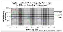 |
Figure 3 |
The shelf life and charge retention depend on the self discharge
rate and self discharge is the result of unwanted chemical reactions
in the cell. Chemical reactions internal to the battery are driven
either by voltage or temperature. The hotter the battery, the
faster chemical reactions will occur (see Figure 3). High temperatures
can thus provide increased performance, but at the same time the
rate of the unwanted chemical reactions will increase too resulting
in a corresponding loss of battery life. Similarly, adverse chemical
reactions such as passivation of the electrodes, corrosion and
gassing are common causes of reduced cycle life. Temperature therefore
affects both the shelf life and the cycle life as well as charge
retention since they are all due to chemical reactions.
Maintenance - Adding Water to Flooded Cell Batteries
The electrolyte in lead acid batteries is a dilute solution of
25% sulpheric acid in water. As the lead-acid cell reaches a full
state of charge, the water in the electrolyte is broken down into
hydrogen and oxygen gasses by the recharging current. These gasses,
along with some acid, escape from the vent on the top of each
cell. This process, called "gassing", accounts for the
water lost from the cells. High temperatures (90oF), high rates
of recharge, and elevated voltage limits (2.44vdc per cell) all
increase the amount of gassing that can occur during the recharging
process. If all the cells in a lead-acid battery are to be fully
charged, then a certain amount of gassing will take place. It's
up to us to deal with this situation. We add distilled water to
the cells to make up for the water hydrolyzed into hydrogen and
oxygen.
Never top off the water
of cells that aren't fully charged. This presents a dilemma
to cruisers who often only charge to 80% of the battery's capacity.
There is a product on the market that constantly maintains
water level in the cells of the battery from a reservoir, and
touts its convenience for the user. Really it's just
a convenient way to shorten battery life, because overfilling
with water will inevitably lead to acid spills and loss of electrolyte
when you do fully charge.
Ideally we would like to capture any water/acid that boils off
the cells, condense it and return it directly to the same cell,
as this would keep the cell chemistry as stable as possible over
time under all conditions. There are products that help do that.
Water Miser caps and Hydrocaps replace the regular cell vent
cap on a battery. When the cell is gassing, the hydrogen and oxygen
gasses are vented into the cap, which captures and condenses the
gases returning the recombined water to the cell. Hydrocaps use
a catalyst to recombine hydrogen and oxygen gas back into pure
water. (A chemical catalyst is a substance which facilitates a
chemical reaction in other substances, in this case hydrogen and
oxygen, without actually participating or being consumed in that
reaction.) The resultant water is then dripped back into the cell.
This reduces both the danger posed by out gassing explosive hydrogen
and the frequency of replenishing water in the cells. The catalyst
used in Hydrocaps is effective for about 8-9 years before prolonged
acid exposure causes the catalyst to deteriorate requiring replacement.
Water Misers trap water and acid vapor reducing water loss by
50-80%, Hydrocaps recombine the gasses and reduce water loss by
90%. Hydrocaps do get hot when the charging cycle causes out-gassing,
heat being a by product of the chemical reaction taking place.
Hydrocaps should be removed when equalizing, but proper equalization
needs to take place with abundant shorepower and with the proper
test equipment. Actually improving your charging system may almost
eliminate the need for equalization charging.
"We've been using Hydrocaps for 15 years to reduce battery
water consumption and help keep the battery tops and terminals
clean of acid buildup. This will cut down on water consumption
and gas emission." - Steve Dashew
In an independent test of an off-grid home solar system; a battery
bank of Trojan L-16s had their caps changed to Hydrocaps and after
2 months operation required no additional water, this despite
previously consuming 1.5 gallons in a similar period without Hydrocaps,
Off-grid homeowners, RV owners, and cruisers that use Hydrocaps
report only adding water annually or semi-annually when they clean
the tops of the batteries of any acid deposits, dirt and dust.
This is a significant improvement that avoids getting you in trouble
with your maintenance regimen.
Connecting Your Battery Bank - Avoid Multiple Parallel
Strings
The ideal battery bank is the simplest, consisting of a single
series of cells, sized in amperage capacity for the job, with
power taken off at each end, (eg. negative on one end and positive
on the other end). Higher capacity batteries tend to have thicker
plates, and therefore greater longevity too. Having fewer cells
reduces the chance of randomly occurring defects, and reduces
charge equalization problems within cells. Suppose for example,
that you require a 600 amp-hour bank. Since the best price per
Ah available in the battery market is the flooded cell golf cart
battery (6v, 200-225 Ah) most cruisers will arrange their battery
bank in a series/parallel string to get 12volts at the desired
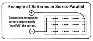
amperage. You can approximate the 600 amps by using 3 series/parallel
strings of T-105 golf-cart batteries (225 Ah each) as shown in
Figure 4, or 2 series/parallel strings of the larger L-16 deep
cycle batteries (390 Ah each) or by a single series string of
large 2v, industrial traction batteries of 600 Ah capacity per
cell.
Using parallel strings invites problems in maintaining equalization
within the battery bank unless they're connected correctly. Under
no circumstances is it advisable to install more than three parallel
battery strings. The resulting bank will tend to
lose its equalization, resulting in accelerated failure of any
weak cells. Weak cells will be difficult to detect because they
will "steal" from the surrounding cells, and the system
will suffer as a whole and will cost you more in the long run.
Here are some precautions to take when wiring two or more strings
of batteries in series/parallel:
- The goal is to maintain all of the cells at an equal state
of charge. Cells that tend to receive less charge are likely
to fail prematurely. This can take years off of the effective
life of the battery bank. A fraction of an ohm of added resistance
in one battery string can reduce the life of the entire string
so measure it and juggle batteries and/or cable lengths to get
them as close to equal as possible.
- Connect the two main cables to opposite corners of the battery
bank, and maintain symmetry in wire size and lengths. This will
help to distribute current evenly through the bank.
- Arrange batteries to maintain even temperature distribution
throughout the bank. Avoid uneven exposure to heat sources.
Leave at least 1/2 inch of air space around each battery, to
promote even cooling.
- Apply a finish charge at least every 3 weeks (bring every
cell to 100%
charge).
Preventing Corrosion
In flooded battery installations, corrosion of terminals and
cables is a nuisance that causes resistance and potential hazards.
Once corrosion gets hold, it is hard to stop, but luckily it is
easy to prevent. Apply a non-hardening sealant to all of the metal
parts of the terminals before assembly. Completely coat the battery
terminals, the wire lugs, and the nuts and bolts individually.
A sealant applied after assembly will not reach all around every
junction. Voids will remain, acid spatter will enter, and corrosion
will begin as soon as your installation is finished.
Special compounds are sold to protect terminals, but you can
have perfectly good results using common petroleum jelly (Vaseline),
which will not inhibit electrical contact. Apply a thin coating
with your fingers, and it won't look sloppy. If a wire is exposed
at a terminal lug, it should be sealed airtight, using either
adhesive-lined heat-shrink tubing or submersible rubber splice
tape. You can also seal an end of stranded wire by warming it
gently, and dipping it in the petroleum jelly to liquefy, and
wick it into the wire.
It helps to put the batteries over a floor drain, or in a space
without a floor, so that they can be rinsed with water easily.
Washing the battery tops semi-annually will remove accumulated
moisture, acid spatter, and dust. This will further reduce corrosion,
and will prevent stray currents from stealing energy. Batteries
installed using these simple protective techniques show very little
corrosion, even after 10 years without terminal cleaning.
Energy Audit - Efficiency First
"Very often I have calculated battery system "size"
to be in the region of 400 Amp-hours for a 40' cruising yacht,
but only if the customer would change the fridge to a high-efficiency
unit." - Rick Young
The first design parameter is to find is your daily amp requirements
by making a preliminary energy audit of at anchor and on-passage
needs. (It's not unusual BTW for on-passage energy needs to exceed
those at anchor, because you'll be using GPS, electronic charting,
AIS, and autopilots etc. on-passage) Initial investigation should
reveal where you could use more efficient equipment, like compact
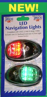
fluorescents, evaporator plate DC refrigeration, LED anchor lights,
etc. The approximate number of kW-hours that may be consumed over
24 hrs provides the parameters for sizing the battery bank.
AC appliances consume enormous amounts of battery power (110v
x amperage x hours of operation), and need to run off inefficient
inverters. Replace AC appliances where DC alternatives are available.
Try to limit the AC appliances operated by inverter to those that
run for short time periods, (eg. coffee grinders, hand blenders,
microwave ovens). Look at alternatives (propane or diesel) to
electric appliances for heating water or cooking which demand
high current for long periods, or plan on powering them directly
with a small AC generator when they're in use.
A spendthrift approach to efficiency will quickly drain even
a large battery bank, forcing you to depend on shorepower or running
a separate generator for long periods. From your daily energy
needs you can begin to design a charging system that will return
that energy to your battery bank.
Battery Decisions - 12 or 24 Volts
If you're building a boat and don't have an existing electrical
system installed this is an important decision that will effect
your wire sizing and selection of equipment. If you have an existing
boat and decide to switch to 24 volts you probably don't need
to rewire since your existing wiring will be carrying less amperage,
but you'll probably want to change out much of the DC electrical
equipment to 24 vdc. Some appliances aren't available in 24 volts,
but lighting, fans and pumps are and will have the same power
demands, but at 24volts require about half the amperage. Often
24vdc equipment is a bit more expensive, sometimes it isn't.
Power in watts = Volts X Amps
12v x 10A = 24v x 5A
Many cruisers base their decision to use a 24vdc system on the
use of an electric windlass or bowthruster, because the high current
these demand requires very heavy gauge wire on a long run from
the battery to the front of the boat. 24volts halves the amperage
and reduces the wire gauge required. I would suggest that there
are other good, even better reasons for using a 24 vdc system
on today's boats. These have more to do with the nature of the
marine market itself, and the increasing use of electronic equipment
on board.
"There are but two ways to build truly reliable electronics:
large volume or high cost, either of which are challenging in
the small, fragmented marine world." - George Walner,
electrical engineer and designer/owner of 'Electra'
The marine market is really tiny especially compared to the automotive
and truck markets, where R&D costs can be spread over millions
of units or where volume and the demand for reliability have improved
the product. Always look for alternatives from larger more demanding
markets before buying anything with the word "marine"
on it.
The marine market is really tiny especially compared to the automotive
and truck markets, where R&D costs can be spread over millions
of units or where volume and the demand for reliability have improved
the product. Always look for alternatives
from larger more demanding markets before buying anything with
the word "marine" on it.
Here are my reasons for deciding on a 24vdc system:
- Electronic equipment is very sensitive to voltage fluctuations,
which are typical in a nominal 12 volt battery bank, (voltage
varies from about. 11.2-14.4 volts). The military is dependent
on an extensive array of on-board electronic equipment in their
vehicles and have standardized on 24v electrical systems. To
power electronic equipment they use DC-DC converters, that can
withstand extremely harsh environments, to step down from 24v
to 12v so any voltage fluctuations at the battery bank can be
virtually eliminated at the 12v electronics. Since the DoD paid
for the R&D and obtains this equipment from COTS (common
off the shelf) contracts, the result is reliable cost effective
commercially available converters. (3)
- Telecommunications systems that are off-grid, (ie. antenna
and cell-phone towers), are typically based on either 24 or
48vdc systems. DC to AC inverters designed for use in cell phone
towers are rugged, modular (combining to supply higher amperage),
hot swappable and very reliable. The cell phone companies that
operate them demand high reliablity. (3)
- Generating DC electricity using a high output alternator on
the propulsion engine is often the cheapest and most cost effective
charging source. We can dramatically improve the efficiency
of the typical truck alternator by operating it at 24 volts.
It turns out that using 12 volts places an efficiency limit
of about 50% on the typical "claw-pole" automotive
alternator. This was considered acceptable in the 60's when
fuel prices were low and the switch to alternators was motivated
by the need to generate higher currents at idle to power accessories.
Running a 12 volt alternator at 24 volts can improve its efficiency
dramatically. (More about this when I cover alternators and
how they work.)
Battery Bank Sizing – Making a Compromise
Steve Dashew is very smart and he's been working on and refining
solutions to charging systems on cruising boats for a long time.
I was always intrigued by his choice of "traction batteries"
(used in forklifts) and the high amperage he typically selected
for his battery banks, (800Ah on Beowolf, 1400Ah on Windhorse,
and recently 1200Ah on the FPB64). This isn't just overkill; there
is logic at work here. Traction batteries unlike golf cart batteries
are designed to be discharged regularly to 20% rather than 50%
of their capacity, giving him an extra 30% of capacity available
for use should he want it. (In other words, this increases his
flexibility in staying longer in an anchorage
without charging.)
Dashew's battery banks are composed of individual 2 volt cells,
which can be used to create a simple series string; that is more
reliable than a series/parallel arrangement. Though very heavy
in total, and quite tall, each 2v cell is separate, so lifting
a single cell is within the capability of one or two fit men (depending
on size). The cells are available in a variety of amperages so
he selects the size to equal his desired amperage for the entire
battery bank. Like off-grid solar powered homes, he sizes his
battery bank to power the boat for multiple days. On the FPB64
he has 80% of 1200 Ah available (960 Ah) or enough for a daily
load of 320 Ah for 3 days. He plans on powering to a different
anchorage or running his generator every third day to recharge
his batteries. The generator also provides power for electric
cooking and doing laundry along with battery charging. (Some small
generators can drive a separate truck alternator for battery charging.)
To recharge his batteries when powering, Dashew uses twin nominal
150A 24v alternators with electronic controllers to equally divide
the output needs. His is the kind of compromise you almost never
read about in boating magazines, but makes perfect sense.
I have to admit being puzzled by the fact he didn't use the large
roof area of the FPB series to mount solar panels, which could
provide the area to supply some of his daily needs, toping off
the batteries regularly at absorption and float current levels.
That would make it very much like an off-grid solar home with
generator back-up. His boats have the space for a large battery
bank and he mounts them so as to balance the boat's trim. I have
to admit being puzzled by the fact he didn't use the large roof
area of the FPB series to mount solar panels, which could provide
the area to supply some of his daily needs, toping off the batteries
regularly at absorption and float current levels. That would make
it very much like an off-grid solar home with generator back-up.
His boats have the space for a large battery bank and he mounts
them so as to balance the boat's trim.
You're probably wondering what this high dollar example has to
do with the much smaller, less demanding and hopefully cheaper
electrical system on your boat. It is illustrative of how you
can make compromises in electrical and charging system design
to achieve a particular cruising goal. In Dashew's case, he wants
his average 3-day stay in an anchorage to be largely free of the
noise and attention demands of a generator, but doesn't want to
give up much in creature comforts, including a washer/dryer and
DC air conditioning, so he developed a compromise to suit.
Let's use Rick Young's typical 400 Ah 12v battery bank on an
efficient 40' cruising boat, to look at an alternative compromise.
Figuring that the bank is sized for a daily load of about ¼
the size of its capacity (which is typical) it suggests about
100-150 Ah daily load @ 12 volts. Let's work these hypothetical
numbers to try to achieve a different compromise. We'll start
by switching to a 24 volt system, so our daily load will change
to about 50-75 Ah. Ideally, we'd like to restore much of that
load using solar power, but we know we'll never have the area
available for bulk charging; for that we'll rely on a high output
engine driven alternator which we'll need anyway on passages to
recharge the batteries.
What if we increased the Ah capacity of our battery bank so that
our daily load could be supplied by solar panels at absorption
cycle current levels. That would reduce our solar charging system
to about 20% of the battery banks capacity. What size bank would
we need?
75Ah / 0.20 = 375 Ah
Let's use a battery bank of L-16s (390Ah). 4 L-16s in a series
string is taller and heavier than T-105's but has about the same
footprint. How many days can we operate without charging?
390Ah * 0.50 DoD / 75Ah per day = 2.6 or about
2½ days
Suppose we change to 420Ah 2v traction batteries. Will their
ability to handle an 80% DoD extend our days without charging?
420Ah * 0.80 DoD / 75Ah per day = 4½ days
We still have two unanswered questions:
1. Can we design a bulk charging system that can provide the
200-320 Ah needed to bring a 400 Ah battery bank up from 50-80%
DoD?
2. Can we fit a solar array on the boat to provide about 75Ah@24volts?
Let's try to answer those questions in that order alternators
first.
Alternators and Regulators
How alternators work - The typical automotive
"claw-pole" alternator uses a magnetic rotor (turning
element) consisting of either permanent magnets or more commonly
electromagnets with a field current in their windings. A stator
is placed around the spinning rotor. Within limits, the stator
wiring determines the amperage output of the alternator. An alternator
generates 3-phase alternating current (AC). The AC current comes
off in three legs and then a group of 6 diodes (rectifier) are
used to convert the AC to DC. "P" type alternators use
electromagnets in the rotor and have two field brushes that pass
the field current to the spinning rotors. The voltage regulator
monitors the battery voltage and varies the field current to alter
the amount of current and voltage supplied to the battery.
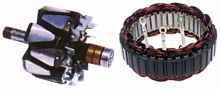 |
Left: Rotor with copper slip rings for brushes
Right: Stator with 3 Phase Output |
The USCG has seen fit to certify as "marine" only brushless
permanent magnet alternators, to avoid sparking and fire on gasoline
powered boats. Diesel engines don't have fumes that ignite and
so non-marine alternators work fine; indeed to achieve an Amp-hour
or 3-step charging regime requires altering or interrupting the
field current and is the simplest way to control the output of
the alternator. Dropping the "marine" designation also
allows us to take advantage of the economies of scale permitted
by the truck market.
Truck alternators aren't designed to charge banks of deeply discharged
batteries. Instead, they're designed to maintain them against
a given load. Take an emergency vehicle, as an example. It might
have 100 amps of load with various devices in operation, with
the engine idling. Supplying the current to recharge after starting
isn't demanding, so the battery never really gets deeply discharged
and the alternator loafs along, with the field current cycling
on and off, which helps keep the alternator cool. In fact the
voltage regulator is built into automotive and truck alternators,
and actually monitors alternator temperature to keep them cool
since diode failure from heat is the #1 cause of alternator failure.
The internal regulator that comes with the alternator can't do
3-step charging, so it gets tossed out in our application.
Now come on board a boat with a large battery bank and an intermittent
charging regimen. When the alternator starts up, it has to go
to full output, sometimes for hours on end, to get the batteries
back up to their charged state. This means the current flowing
to the alternator field is on constantly - what is called full
field operation. There is no chance for the alternator to cool
down, except via the air being pulled through it by its own fan.
(Tip - Always match the fan assembly to the direction your engine
turns, though bi-directional fans are available for many alternators
they're much less efficient than a directional fan.)
To meet the current needs for bulk charging on a cruising boat,
a high output alternator will spend much of it's time in full
field operation. Two small frame high output alternators (90-100A)
will not be as reliable or as efficient as one 160A large frame
alternator. The large frame truck alternator has much more volume
with which to accommodate magnetic flux saturation of the field,
better cooling and bearings that are about 4 times "stronger"
than those of small frame alternators; all these advantages in
a package only 1.5 inch larger in diameter.
Alternator Heat Management - The majority of
the heat from an alternator comes from the rectifier diodes, which
convert the alternator's AC power to DC. Most alternators draw
air from back to front. Unfortunately, the air behind the alternator
in most installations is typically beside the exhaust manifold
of the engine - the hottest place in the engine compartment. Alternators
with internal rectifiers can get so hot, you could fry an egg
on them, and many can get hot enough to melt the epoxy insulation
on the stator wiring when operated at fullfield current.
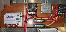
| This is the rectifier board on Steve Dashew's
FPB64, taken from his Setsail website. It shows the two remote
mounted (fan cooled) rectifiers for the Electrodyne alternators.
These are installed remotely outside the engine room. The
Smart voltage regulator is mounted between the rectifiers. |
 |
Heat reduces output, and shortens the life of the alternator.
Removing the rectifier diodes from the alternator body, and putting
them in a fan-cooled box removes the heat source from the alternator
body and the diodes from the hot engine compartment, greatly increasing
the durability and life of both. There are kits available
to do this, or you can just remove the alternators
rectifier and replace it with an aluminum spacer (with holes for
cooling) if necesssary, and mount the rectifier in a fan-cooled
enclosure outside the hot engine room.
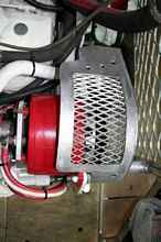 |
Here's a photo from Dashew's FPB 64. Instead
of the solid belt guards that come with the Luggar engine,
they've built expanded metal guards in front of the engine
. |
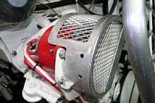 |
and around and in front of the belt of the alternator
that permit cooling air flow |
We thus far have stripped our truck alternator of everything
but the rotor, stator and field brushes. If you buy a new high
output alternator, the rectifier and regulator are often mounted
internally or in some cases on the back of the alternator. An
even cheaper alternative would be to buy an alternator core from
a wrecking yard, clean it up, strip out the rectifier, toss the
regulator, replace the brushes and bearings and any defective
parts (if necessary). Warning
- It is very important when stripping an alternator of these electrical
parts to make sure that all electrical connections are well fastened,
free from contact with the moving rotor and insulated from the
alternator casing. This is particularly true when removing the
rectifier diodes. An alternator repair shop should be capable
of performing this for you if you explain what you intend to do
and why.
Alternator Selection - About the most amperage
you can get reliably from a12vdc alternator is 160A, which makes
the Leece-Neville 110-555 "triple nickels" one of the
better off-the-shelf alternatives on the market. (Leece-Neville
was purchased by Prestolite who changed the part no. to 8LHA2070JHO
for a typical12/6 mounting lug arrangement or 8HLA2070PHO for
a pad mount.) These are frequently used by the manufacturers of
motorcoachs and large RVs. The large frame Delco CS144 140A alternator
was used for many years in delivery vans and ambulances and has
a good reputation also.
DC refrigeration systems often trigger the need for larger battery
banks. Many cruisers turn to generators as a charge source, but
as we've seen selecting a typical AC charger can double the time
to charge over a 3-step charging regime. Most AC chargers are
made to be connected to shorepower so often provide much lower
amperage than a high output alternator can, which also increases
the time to charge. Running a generator for long periods in most
anchorages certainly won't make many friends among your fellow
boaters.
If you intend to recharge a large battery bank you can resign
yourself to longer charge times or use some ingenuity to come
up with a better solution. One option is to temporarily split
the typical series/parallel battery bank into two independent
12v banks for charging and thus cut the current demand of each
bank by half. A split charging regime can work especially well
when using two battery chargers with a small generator for power,
as long as the charger and battery split are completely independent.
Another alternative is to mount twin alternators on the engine.
Boats with twin engines do this using an electronic controller
to balance the alternators output, like Ample Power's Dual Alternator
Controller
(DAC). (If you attach both alternators without an electronic controller
to balance the load, one alternator will work at full output and
the other will loaf along - it just doesn't work.) Where fuel
consumption and engine operating hours are important this doubling
of available charge current can keep the time for bulk charging
short and still do it with truck alternators (cheap).
Another option, particularly for people building their boat,
is to decide to install a 24vdc system. Bob Gayle wrote a white
paper4 about improving the efficiency of a typical truck alternator
and thus its power output. He switched a Leece-Neville110-555
alternator to charge at 28.8vdc. The measured output for this
alternator were 130A @ 14.2v (1.85 kW) at 3400 rpm. With the regulator
fooled into using a 28.8 volt setpoint for output, the alternator
produced the same 130A @ 28.8v (3.74kW) at 3400 rpm at full field
current, almost doubling its power output just by allowing it
to operate at the higher voltage. No rewinding was needed since
the windings are running the same current. Bob used an old 12v
Balmar regulator monitoring voltage from the middle of the battery
bank, so the regulator thought the alternator was generating 14.4v;
instead of the actual 28.8 volts being delivered across the entire
battery bank, (this works easier using a regulator that allows
a 28.8v setpoint).
Such a configuration can easily provide the bulk charging for
a 24v 225Ah bank, or even a 24v 390Ah bank composed of L-16 batteries.
Two alternators with the Next Step regulator and Dual Alternator
Controller can charge even large traction battery banks. We know
this because Dashew uses a similar arrangement to charge the 1200
Ah bank on the FPB64. The difference is just one of Dashew's two
Electrodyne alternators retails for $1,242, while 2 L-N "triple
nickels", the Next Step regulator and DAC would retail at
$954 and you can find "triple nickels" for a lot less.
Selecting the Pulley Ratio - The pulley ratio
is determined by the following equation:
Pulley ratio = Crankshaft Pulley diameter / Alternator Pulley
diameter
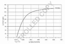
Notice that the output curve in Figure 5 varies with speed in
RPM and that to run the alternator near its peak output requires
a shaft speed of 3500-4000 RPM which is much faster than most
diesel engines will turn at cruising speed. The cut-in speed for
this alternator is 1000 rpm for 12v, (2000 rpm if run at 24v),
and the manufacturer has an 8000 rpm continuous rating for this
alternator.
For example: I've determined that the cruising speed of the Isuzu
4LE2 engine should be about 1800 rpm. The Isuzu's maximum speed
is 3000 rpm. The alternator needs to reach the cut-in speed of
1000 rpm for 12v (2000 rpm for 24v) at an idle speed of 800-900
rpm for a ratio of 1.25:1 or greater (2.5 to 2.67:1 for 24v).
I would want to turn the alternator at 3400-4500 rpm alternator
speed at 1800 engine rpm - a pulley ratio of 1.88:1 for 12v (2.5:1
for 24v). At 3000 rpm the alternator would be turning 5640 rpm
(7500 rpm for 24v), still below its 8000 rpm limit.
The power requirements of big alternators put big strains on
the drive belts, alternator brackets, and pulley tensioning devices.
Add in the power pulses which are inherent in all diesel engines,
and it takes muscular engineering for all of this gear to stand
up over time. Switch to dual V belts is mandatory, or using "poly-V"
or ribbed belts and a serpentine drive is a better idea that can
also reduce tension requirements. They're more reliable and better
at power transmission.
| Figure 5 Prestolite 8LHA2070 / Leece Neville
110-555 |
 |
Alternator Mounts Should be Made in Steel -
Should you decide to add a second alternator you'll need to make
mounts. Steel is used by every engine manufacturer to build alternator
mounts for two reasons:
- Steel has vibration resistance that provides years of trouble
free service.
- Steel matches the engine’s galvanic voltage potential,
thus preventing
rust. Dissimilar metals and should not be mixed in a marine
environment.
Delco makes universal welding brackets for alternators, (2"
mount - unplated for welding). It should go without saying that
you should measure your alternators mounts and compare them to
the brackets before buying them. These can be welded to a custom
supplied engine bracket, and the heavy duty curved belt tension
extension bracket, (3/8" thick x 1-1/4" wide, unplated).
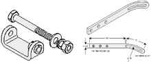 |
Left: Delco Part # A300 $17
Right: Delco Part # A220 $29 |
Finding the HP and Torque Required for a High Output
Alternator
130 amps (@3400 rpm) x 14.4 volts = 1872 watts
1872 watts / 745.7 watts/hp = 2.5 so figure 3 hp
3 hp x (5252 / 900 rpm) = 17.5 ft./lbs.
The same current @ 28.8v or twin alternators would take 2.5hp
*2 or 5hp
Voltage Regulator - During the bulk charge step,
the battery can accept most of the alternator current and convert
it back to available capacity. Once the battery nears a full charge,
excess charge current becomes heat. Small at first, the heat begins
to accumulate in the mass of the lead plates. As the heat accumulates,
temperature of the battery begins to rise. The current through
the battery begins to double for every 18oF increase in temperature.
That means more power is dissipated in the battery which means
more heat is generated, which means more current flows, which
means more heat - all leading to thermal runaway.
If you're lucky you won't be looking at the battery when the caps
blow off with acid following. To avoid this absolutely requires
a voltage regulator to control the alternators output.
The voltage regulator monitors the battery's voltage; if the
battery needs more power the voltage regulator changes the field
current to the rotor coils. If the regulator senses a large discrepancy
between the battery voltage and its setpoint, it sends maximum
power to the rotor. If the regulator senses a small need at the
battery it will send minimal power, causing the alternator to
produce less. The better regulators will also accept battery temperature
sender input to prevent thermal runaway.
Unlike the rectifier, the alternators output amperage never goes
through the voltage regulator. The area of concern when changing
to a high output alternator is the amperage draw of the rotor
and consequent change in the field current amperage. The voltage
regulator is also sensitive to heat and should be mounted outside
the engine compartment, the length of the cable run and the current
determine the wire gauge required for the field current. Voltage
regulators do have a field amperage rating and because it has
direct contact with the rotor you should be concerned with the
amperage draw of the rotor in order to size the wiring accordingly.
If the amperage draw of the rotor is greater than the rating for
the voltage regulator the regulator will fail. Some alternators
have the brush mounts built into the body of the regulator, on
others they're separate and permit easy removal of the regulator.
A separate switch for the field wiring can be used to "shut
down" the alternator. The field current controls whether
the alternator is turned on and generating AC voltage. A dry cell
battery, appropriate for providing the field current, can also
be wired up to the switch as a backup to insure that the alternator
will charge a dead house battery bank if you can get the engine
started. (This is problematic if your engine has common-rail injectors
or "glow-plugs" which require a lot of current).
| Ample Power’s Next Step Regulator 12
or 24vdc ($299) |
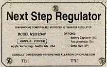 |
3-step voltage regulators that emulate the Amp-hour Law are few
and unfortunately expensive. Ample has a good reputation for reliability;
the Next Step 2 w/ battery temperature sensor is both 12/24v capable
($299), and the V3 (12v -$449, 24v $499) has better field current
protection. Balmar have only fair reliability with several SSCA
members reporting replacing multiple units or "losing programmed
settings after a few days", wire size may play a role in
programming loss (?), and the mounting location may play a roll
in failures (heat sensitive). Ample and Balmar both accept battery
temperature sensor and alternator temperature sensor input to
control field voltage. The best 3-step alternator regulators are
ones which allow you to set the absorption voltage, the float
voltage, and the time-to-float independently and accept a battery
temperature sensor to prevent thermal runaway.
Procedure for Adjusting Absorption Charging Voltage
During absorption charging the voltage remains constant and the
current gradually tapers off as internal resistance increases,
so the charger needs to put out a higher voltage. Voltages during
this stage are typically between 14.2 - 15.5 volts in a 12 volt
system, (28.2 - 31 volts in a 24vdc system) and being able to
make small 50 millivolt changes can dramatically change the charge
current supplied. Our goal during absorption charging is to vary
the charge voltage until the charge current matches the "missing"
amp hours from the battery. Like a fuel tank you use the battery
monitor to determine the desired amount of current at any given
moment; if you're down 90Ah then you want to feed the batteries
90A of charging current. Adjusting the absorption voltage to match
the missing amps will result in a closer approximation of the
Amp-hour curve. This can recover lost battery capacity in batteries
that have only been partially charged and degraded. Here is the
procedure to follow:
1. Pick a time when the number of Amp-hours missing is slightly
less than the maximum charge current capability of your charge
source.
[Note: We know that the battery charger should
be sized to deliver approximately 25% of the Amp-hour rating of
the bank to guarantee sufficient current density to the discharged
plates for uniform conversion of the sulphate formation to oxide
formation. Such "good" charging may make a life difference
from as little as one year to 10 years.]
2. Increase the charge voltage to as high as possible. Note the
charge current. If the current is say 40A and you have 38Amp-hours
missing then leave it there, it doesn't matter what the
voltage is.
[Note: Be sure to check that your shore charger
or alternator regulator can allow the user to set the upper voltage
range well above 14.4v, 14.6v is a minimum. Also check to see
just how easy it is to make such changes.]
3. Keep watching the charge current versus the number of missing
Amp-hours and if the charge current exceeds the number of missing
Amp-hours by say 10% or more then consider lowering the voltage
again to make the numbers match. If the decreasing charge acceptance
current "tracks" the missing Amp-hour number within
10% or so you are in luck.
[Note: On succeeding charge cycles the voltage
might have to be set slightly lower because the battery has already
recovered lost capacity due to a better acceptance charge. As
the battery heads towards full the charge current acceptance of
the battery decreases tending to not make you have to change the
charge voltage perhaps at all.]
Adjusting Float Charging
Once the battery is back to near 100% the charging system switches
to float charging. Float voltage is determined by the acid concentration
and temperature period; 13.7-13.9v is a good float value for 12v.
There is a simple formula describing the at-rest cell voltage
as a function of the specific gravity of the electrolyte. The
time to transition to float is when you are almost full and you
will note a complete lack of tracking:
- For example, the charge current is 5A and you are only missing
2Ah.
- You should note at this time that no significant
temperature rise has occurred in the battery.
If it has then on the next cycle go to float earlier. Once you
have attempted Amp-hour law charging and the battery has been
on float, say overnight for shorepower chargers, (or all day
for solar), put the charger back on at the same drive level
that you used to get maximum current from your charger.
Once you have attempted Amp-hour law charging and the battery
has been on float, say overnight for shorepower chargers, (or
all day for solar), put the charger back on at the same drive
level that you used to get maximum current from your charger.
If the capacity of the battery has been recovered then the charge
acceptance current will be near zero - about 100mA per 100 Amp-hour
rating of the battery or less. If you observe this then the internal
resistance of the battery is minimum and the capacity is likely
to be maximum.
- Manually zero out any accumulation in your battery monitor,
if it doesn't zero automatically.
- From here you begin your discharge cycle and the end reading
will be accurate.
You can repeatedly get away with bulk charging only to approximately
80% capacity, if you periodically (once a month min.) fully charge
the battery bank as described above, you'll increase its service
life by years.
Time of Recharging
The math involved solves this equation:
Ic = Im(e-t)
Where:
Ic = the charge current available
Im = the number of Amp-hours "missing" from the bank
T = charge time
One integrates Ic versus time to get the total accumulation of
Amp-hours for a time period. One quick way to visualize this is
that one can get about 63% of Im in the first hour and one can
get 63% of the value of the remaining value of Im (at the end
of the first calculation) in the next hour. This will give you
a very close approximation assuming that the battery is charge
accepting, knowing when the charger becomes voltage limited, thereby
not being able to put out rated current.
AC Battery Chargers
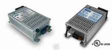 |
Iota DLS-90 (12v) and DLS-27-40 (24v) Battery
Chargers with an internal IQ4 Charger control that does 3-step
charging ($185 - $400 ) |
I suggested earlier that for AC battery chargers powered by a
generator one way to reduce the charge time was to split a series/parallel
battery bank into two 12 volt banks, which halves the amperage
required for each bank, and use two high amperage 3-step chargers.
Join your two independent banks with a battery selector switch;
wiring one charger to each bank. This way each charger will have
the best opportunity to deliver rated current.
Chargers for use with a Honda EU2000 Generator - The small Honda
generators are small, light, relatively quiet, and have a fuel
pump capable of drawing gasoline from a larger tank or Gerry can,
all of which makes it more acceptable to cruisers running them
in an anchorage. Using Iota DLS-75 chargers the absolute maximum
current draw is 18A at the low end of the AC input voltage range.
That is the approximate output of a Honda EU2000 generator. Each
charger is connected to a separate 20A AC power circuit. (You
use an external IQ4 controller with the Iota chargers to make
it into a 3-stage charger. The IQ4 controller adds about $30 to
the cost of the chargers.)
The charging voltages on the Iota can be changed, but not independently.
There is a single screw which lowers/raises voltages used for
all 3 steps. On the older Iota chargers, the screw is accessible
from the outside of the charger, and for the newer Iota chargers
one needs to open the charger to access the screw.
Rick (Young) is the person who helped me to understand how
to hook up my two Iota chargers. Here is how it is set up:
4 Trojan T-105's are wired up in series/parallel arrangement
to give 2 banks of 12vdc. I have a 5kw diesel genset that can
power two 120vac 30A circuits . I have each Iota DLS 90 hooked
up to a single bank (2 Trojan T-105s wired in series). During
charging, I isolate the battery banks and run both Iota chargers
at the same time, allowing each DLS-90 to independently charge
its own battery bank. When charging is complete, I then put both
banks in parallel and drain them as a single bank, enjoying the
benefits of a slower drain rate since I'm drawing from all four
T-105s at the same time.
The system has worked flawlessly for us. The batteries, surprisingly,
are behaving like new still, a year later.
Everything is working very well now, these are well-built
switching power supplies. They don't get very hot. Thank you all
for helping me to select the proper equipment at a price that
didn't break the bank. I am very satisfied with the setup.
I wired one Iota 90 into each of my 30amp circuits. This
allows me to run both chargers and turn on an item or two during
bulk charging on either 30amp circuit. More flexibility than having
them both on one circuit.
Iota stands behind their products as well. I bought a DLS
55 w/IQ4 from a member here and it quit a month later. Iota replaced
it with a brand new unit - no questions asked even though it was
bought second hand. Now there's a company that really stands behind
what they make! I wouldn't hesitate to recommend or buy again.
The whole idea is that both chargers work at the same time on
the separated banks. Keep in mind that even with the battery selector
switch in "both" the chargers can still be operated
at the same time with their outputs essentially in parallel, you
just have an overall reduced number of Amp-hours being delivered
compared to operating with the two chargers because their outputs
won't be balanced.
One other way to charge batteries with a generator is by using
it to drive a truck alternator. This was what Bob Gayle was investigating
in his white paper4. He had a small Chinese Chagfa S195 IDI diesel
engine mated to an ST 7.5 AC generator and he drove an L-N "triple
nickel" alternator off the front pulley for battery charging.
This works much better for DC battery charging than any arrangement
of AC battery chargers, as your existing 3-step regulator can
be switched between the propulsion engine's alternator or the
generator's alternator for operation.
Alternative Charging Sources – Solar, Wind and
Towed Water Generators
While engine driven alternators can provide your bulk charging
needs, few independent charge sources work better for absorption
and float charging than solar panels. Photovoltaic (PV) solar
provides it's charging over a long time period (about 4 hours/day
from 10am to 2 pm), but with limited current, so solar is an excellent
charge source for the higher voltage/lower current demands of
absorption and float charging, which also needs to be supplied
slowly over an extended charging period. If your daily current
draw can be topped off during the day by solar you'll not only
increase your quiet time at anchor, you'll improve your battery
life dramatically (remember the DoD chart). If you reduce your
draw periodically by doing some shore based sightseeing a solar
array can replace the current draw of a refrigeration system and
give your batteries a long trickle charge to 105% capacity to
improve their life, all without demanding attention, or annoying
your neighbors, while you're off enjoying yourself. The biggest
problem with this rosy picture is finding the area (and the money)
for the solar panels needed to generate the power.
Unless you have a large catamaran you may have difficulty finding
sufficient area on a boat to mount enough solar panels to meet
your absorption charging needs, but getting sufficient area to
provide the demands of DC refrigeration is easier. This may change
in the near future. The solar photovoltaic (PV) industry is undergoing
a change from silicon panels to thin film CIGS panels, which should
significantly reduce the cost/kW for generating power down to
$0.50/kW. Firms like Nanosolar have developed a PV "paint"
that is printed onto thin sheets of aluminum using large printing
presses. The cells are then placed in a sandwich of insulating
glass. All of Nanosolar's current production from their San Jose
plant is being shipped to Canada for utility sized installations.
Konarka is another firm making flexible CIGS panels using heavy
mylar insulation, all their current production is going to produce
"utility" sized panels. It will be awhile before we
see these panels trickle down first to the residential grid connected
and then the off-grid markets. Flexible CIGS panels have the potential
to be incorporated into awnings, which will go a long way toward
increasing the area that can be utilized on a boat for electrical
charging at anchor. So the future may be bright, but won't be
around to help us for awhile.
Pulse Width Modulation (PWM) Charge Controllers
were developed jointly by Sandia National Laboratory, Morningstar
and Digital Solar Technology5 to charge batteries using PV solar
arrays. To improve solar battery charging, they operate on a different
principle of pulsing the charge current. The charger is periodically
isolated from the battery and battery open circuit voltage is
measured. If open circuit voltage is above a preset limit, the
charger remains isolated (shunted); when open circuit voltage
decays below that limit the charger is reconnected for short periods
- pulsation. The open circuit voltage, charging current and the
pulse period duration are chosen so that when the battery is fully
charged, the time for the open circuit voltage to decay is the
same as the pulse duration. When the charger controls sense this
condition, the charger is automatically switched over to the finish
rate current, where short charging pulses are delivered periodically
to the battery to maintain it at full charge.
Wind Power - Despite the fact that wind generators
with a decent 15-20 kt wind can generate electricity for battery
charging, they have not been as widely accepted amongst cruisers
for several reasons:
- For them to work you need to anchor in a windy, more vulnerable
anchorage.
- The perceived threat of what might happen if a bird flew into
the fragile blades that are madly spinning over your head, and
the resultant flying shrapnel.
- The noise of the fan blades. An Air-X wind generator can generate
80dB of noise, compared to the 56dB of a Honda generator, (Remember
that decibels are a logarithmic scale, so every 3dB doubles
the noise output). It's no wonder then that George Buehler once
wrote he had to be physically restrained from throwing an oar
blade in a nearby wind generator.
 |
There is nothing to mitigate the need to anchor in windy places
or a "perceived" threat of flying shrapnel - you have
to live with those. The noise you can improve by sanding all the
casting flash off the propeller, and reshaping the leading and
trailing edges to be smooth. If you look at the surface of the
blades with a magnifier you'll see tiny "craters" caused
by air bubbles in the mold process, each of which will tear air
and make noise. You can fill these micro-holes with wax or varnish
to reduce the noise level.
A German firm (Spreco LDA at https://www.silentwindgenerator.com)
started making blades for the Air-X wind generator based on wind
tunnel refinements to the propellers used in the Gossamer Albatross
solar airplane. They now offer a version of the Air-X generator
with all their aerodynamic improvements for 1,140 euros (about
$1,600 or roughly a $300 increase over the standard Air-X marine.
generator). One of the chief improvements touted is a reduction
in noise and improvement in efficiency in light winds.
Towed Water Generators are described by Francis
Kinney in "Skene's Elements of Yacht Design" (1973)
and by Steve and Linda Dashew in "The Circumnavigator's Handbook"
(1983). Intermezzo II his first Deerfoot design had a separate
through hull for a prop powered alternator. Some people today
are pushing the idea of hybrid (electrical) propulsion by touting
the idea of "regenerative sailing" using the propulsion
prop to generate electricity. Anyone considering this should note
that Dashew never used one on any of his subsequent designs. Anyone
attempting this will discover as I'm sure he did that in practice
it just doesn't work well.
Luckily for us a group of enthusiasts on the Yahoo Electric Boats
Group (https://groups.yahoo.com/group/electricboats/)
have investigated this extensively. One of the first facts they
discovered was that for a towed water generator to work the pitch
of the propeller has to be the exact opposite of a prop designed
for propulsion, (try reversing the propulsion prop around in mid-ocean
when the wind picks up). They also found that the output was far
less than they anticipated, because the water chooses the path
of least resistance and moves around the towed prop like a rock
in a river. Though everyone in this group approached this application
with enthusiasm and ingenuity they found that electric propulsion
is limited to day sailing on small boats with the batteries sized
to get you in and out of the marina, where you use abundant shorepower
to recharge them.
Given the choice between these alternative charging sources I’d
choose to invest in solar every time.
Electrical Installation -The appropriate wire
varies depending on the voltage and amperage output of the alternator
and the distance to the externally mounted rectifier and are shown
in the chart on the next page. Check the alternator output at
the battery at full charge with a clamp amp. You should be able
to trace all the way back from the alternator. The issues start
when the alternator is producing 125A, but the battery is only
receiving 10A, because the charge is leaking along the way through
a parallel path via other devices. Clamp the propeller shaft also
since this is often a source for electrical leakage and consequent
corrosion problems. Ensure that the output cables are adequately
supported and that nylocks (preferably) or lock washers are used
on the studs. Only used tinned copper wire for the cables.
When upgrading to a higher output alternator you should always
install a larger wire between the alternator and battery. Even
with a standard output alternator you will get better performance
and life out of your alternator if you upgrade the main battery
wiring. The original wire just isn't large enough for proper power
transfer. If you are using your alternator to its maximum output
or when you upgrade to a higher output alternator you must increase
the wires size. An alternators ability to send the power it is
making to the battery is directly related to the wire size and
quality of connection between the alternator and battery. A wire
that is too small when used on a high output alternator can cause
the alternator to overheat, burn up and fail.
Another area that receives little attention is the ground. You
must also improve the ground as well. A poor ground will hinder
the alternators ability to send power to the battery and can burn
an alternator up just as fast as an inadequate alternator to battery
wire. You should isolate the casings from the negative output
terminals, never ground through the engine block.
The engine head or block isn't designed to carry large amperage.
Grounding through the engine is the #1 cause of diode
failures, not to mention stray current corrosion out through the
prop shaft. Your ground may be fine when you first install
your alternator but over time corrosion and resistance builds
up in the ground connections. This is why it is best to run the
ground directly from the rear of the alternator to the battery.
Be careful to allow for flexure in the cables leading to the engine
and also provide chafe protection for all cables.
When installing a high output alternator to replace an existing
one you don't necessarily need to rip out your old wiring. You
can piggy back a second wire between the alternator and battery.
The main battery wire connected to the back of the alternator
has power to it at all times, even when the vehicle is shut off.
You connect this wire like normal then you run a second wire between
the alternator and battery. The power coming out of the alternator
will treat the two wires as one, power following the path of least
resistance.
Run the alternator cables directly to the batteries through a
250A fuse on the positive side of the battery. This allows you
to pull the fuse to isolate the alternator for service.
Physical Installation - Ensure lock washers
and Locktite or use Nylocks on all the bolts used. Pay attention
to the belt tension. Too tight and you will prematurely wear the
water pump bearings. Too loose and you get excessive belt wear
and heating on the alternator pulley which transmits to the alternator.
Use this test; when the engine is cool and place a rag on the
alternator fan and rotate the pulley so that the engine crank
rotates (yes, the pulley ratio mechanical advantage will enable
you to do this). If the belt slips the tension is too loose. Tighten
the pulley JUST so that it doesn't slip with this test and you
will be fine. Keep checking the tension over time.
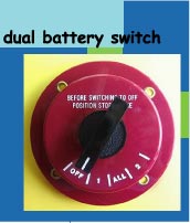
Battery Selector Switch - Be judicious when
choosing a battery selector switch for use with starting motor
currents. Some diesel start motors have locked rotor currents
of 900-1800 Amps and most switches will not reliably carry that
load for years. Cole Hersee has good switches that have proven
to work over time even with loads above their ratings. Perko switches,
however, have failed (in my experience) even with motor loads
within their ratings. Other switches also may not fare well over
time.
Sulphation, Internal Resistance and Battery Aging
Expect very small numbers (< 0.01 Ohm) for a new fully-charged
battery. Expect a non-linear increase in Ri, as the battery discharges.
As noted, you'll want a chart of numerous Ri calculations, at
varying state-of-charge.
References
1 Hydrocap Corp. 975 N.W. 95 Street, Miami, FL 33150 phone:
305-696-2504.
2 “Lead Acid Traction Batteries” by Edward M. Marwell.
Eugene P. Finger, and Eugene Sands © Curtis Instruments 1981.
All rights reserved. Library of Congress Catalog card 81-65733;
ISBN: 0-939488-00-0
https://evbatterymonitoring.com/WebHelp/Battery_Book.htm
3 “E.E. Owner - How a gifted electrical engineer set up
his dream boat”, by Ben Ellison Nov 2007, Power & Motoryacht,
https://www.powerandmotoryacht.com/boat-electronics/electra/
4 "Operation of the Lundell Clawpole Alternator at High
Power Density and Efficiency"; by Bob Gayle; Three Cedars
Research and Development Bob Gayle's white paper on high output
alternator efficiency is only available by joining the Society
of Micro-Cogeneration R&D/Microcogen. info Forum (it's free).
Here is a link to the thread where the paper is: https://www.microcogen.info/index.php?topic=157.0
5 "Battery Testing For Photovoltaic Applications",
by Tom Hund @ Photovoltaic System Applications Department, Sandia
National Laboratories, Albuquerque, NM 87185-0753 https://photovoltaics.sandia.gov/docs/battery1.htm
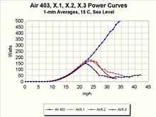
6 "AirX Fails Power Curve Tests", by Paul Gipe, January
29, 2003 https://eduhosting.org/windpics/airx.html
*****
|