| Easier Than A Kitchen
Cabinet - No Doors Or Hinges
At this writing I have almost completed Michael Storer’s
PDR Goose. The hull is complete, the spars
are ready for finishing and the foil laminations are ready for
profiling.
I expect that when the small boat builders see the result of Michael’s
design for extending the hull length of the successful DUCK to
address some of the limitations of an eight foot hull that many
more will be built. There were so many good learning outcomes
for me during the construction that I felt other potential boat
builders might benefit from my experience. I wanted to tell what
has happened as of this writing and not wait until the sea trials
are complete. When that happens I will tell about that, too.
My narrative is based on the digital photos taken during the construction.
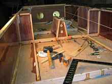
First I want to discuss those items that made the construction
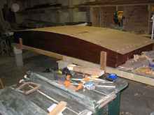
easier and more satisfying. The construction of an adequate building
base, especially a square and modular hull such as the Goose is
most important. See photo 1 for a picture of the all important
base I used for a building platform.
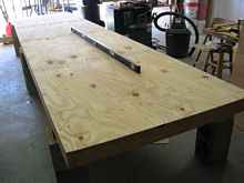
1 |
I assembled this base one Saturday morning with a material’s
cost of about $50. The materials are reusable, since no cutting
(other than some 2x4s) is required. Don’t go too thin on
the plywood. I used 5/8 exterior, (planning on building some plant
shelves for “she who must be obeyed”—hence the
exterior grade. Using the other highly recommended item shown
in the photo – six foot builder’s aluminum level –
the base can be leveled and trued up nicely and used for many
future references. By the way, an added value building a 4x 16
provides an extra work surface. That 4x4 rugged work area will
be greatly appreciated during the build, especially if you are
short on work benches. Examples of clamping and positioning on
this table are shown in other pictures. Thus the special items
for the build are only two – the base and the builder’s
level.
The Duck plans and the Goose supplement are very complete. My
only caution is to be careful switching back and forth between
the documents as you may end up with a ten foot boat if not paying
attention. One very important point faced early on. Michael shows
two versions of shear lines and recommends the straight shear.
I am glad I followed his advice which shows on the plans. The
layout is so much easier and looks really good. My suggestion
to Michael is in later versions of the plan so use the shear for
the base line and use a manufactured edge of ply for reference.
Station perpendiculars would then be erected on the base line.

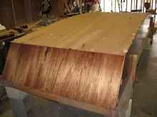
2 |
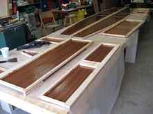
Regarding materials, the builder was most interested in constructing
a hull that would be durable and easy to finish. Achieving a minimum
weight was not a driving parameter. The final choice was Meranti
4mm and 6mm thicknesses. The finishing of this material was facilitated
by the good surfaces and lack of voids, ample return for the higher
cost. On hand was a good supply of seasoned soft maple and I ripped
that to ¾” square for the edge joining. This is all
in accord with the drawings. I found that the chine edging did
not have to be laminated as suggested in the text. The curve is
gentle enough to allow bending of the edging. The sides ready
for assembly appear in photo two. The size of the hull and lines
are emerging.
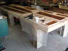
3 |
4 |
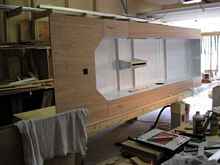
Photos three and four show the completed bulkheads ready for
assembly. My only variance from the specifications was to construct
the forward transom using 6mm Meranti. I also decked the forward
section of the decking with 6mm. The weight penalty was small
and I have a tendency to overbuild which I acknowledge here.
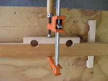
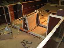
Limber hole construction as shown on the drawings seems labor
intensive to me. My technique (originality not claimed) is shown
in photo five. Clamp a piece of waste the same thickness as the
edging to the frame edge. Locate desired position and drill with
a one inch spade bit.
5 |
6 |
7 |
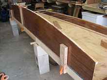
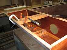
The good part starts with photo six and seven. You can see the
value of a rugged and level building surface in these two photos.
Ample clamping is available; I think that is almost as useful
as a building partner. As this is my first boat, I spent lots
of head time trying to arrive at the best method for doing things.
These findings are included in this narrative to assist and encourage
other first time builders to tackle the Goose. The plans are so
very complete you can be assured of a good outcome. Photo seven
shows frames in place and clamped. Spend some extra time at this
step with the two foot building square to assure proper location
and alignment. As parts are added, from this step forward corrections
become harder to make. Photo seven shows the 4x4 building space
discussed earlier, (place for a coffee cup.)
8 |
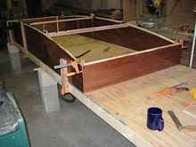
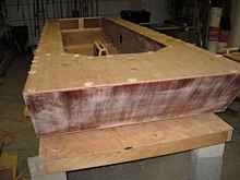
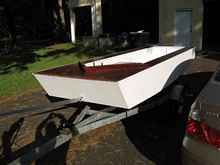
Time for celebration. Photo 8 shows bottom installed and gluing,
using screw pads per Michael. As an aside, do not think of the
scow hull type as a compromise on performance. When you place
your eye forward of the hull and look at the run going aft, you
will see a very efficient water to boat interface. I expect this
hull to be easily driven and quick to plane. Photo 9 illustrates
forward transom in place.
9 |
10 |
11 |
12 |
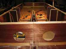
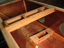
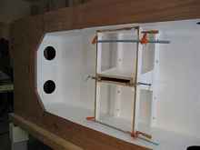
Photos ten, eleven, and twelve show interior construction details,
especially dagger board case and bracing. The alignment string
shown in photo eleven is not offset, my camera is. Check that
string frequently and keep in place as long as possible. Always
be sure that a tool or board is not leaning on the string. Sounds
obvious and is, still happens. Frequent use of winding sticks
help assure good hull alignment. I often used my six foot level
for one stick, placed upon the top of the forward transom. You
will be pleased and amazed at how well your eye will detect twist
in your hull and it is easily corrected at this stage of construction.
13 |
14 |
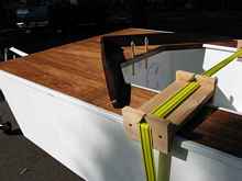
Photos thirteen and fourteen show installation of mast step
and mast partner. Both of these items were fabricated on that
handy 4x4 area (have I mentioned that before?) I made liberal
use of registration pins, actually 4 penny finish nails, predrilled,
to hold parts in alignment prior to gluing. They are easily removed
when glue is cured. These can be seen in photo 14.
15 |
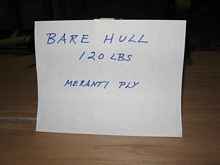
Decking completed, shapes really coming together. Shown in photo
fifteen. At this point curiosity got the best of me and I weighed
the hull. Using a bathroom scale under each transom I found the
total to be 120 lbs.
17 |
18 |
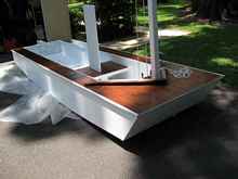
Photos seventeen and eighteen illustrate a hull position that
you will greatly appreciate many times during construction, boat
on side. This is one place where flat sided hulls and a good work
surface (did I mention that?) are really helpful. Central seat
and dagger board case and bottom slot are all performed in this
position. The central seat does not show on plans so this is ad
hoc following e mails with Michael. An observation about the seat.
I was especially pleased at the room in the 12 footer, particularly
the forward cockpit. I am certain that you crazy guys that do
the Texas thing will like that forward space! I can see all sorts
of treatments for storage there.
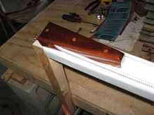
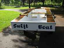
The remainder of the photos detail painting and fittings. The
splash combing was fabricated from a beautiful piece of walnut
I had for many years. I patterned it after the Lightening hull
my father built for me when I was in high school. Those of you
with fathers long gone will appreciate my thoughts as I was building
the Goose. I believe he, as a great boat builder, would be proud
of the results.
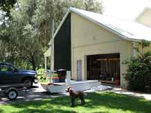
Every boat builder needs a dog. Here is mine. Coco is a standard
male chocolate poodle, shown in one of his favorite positions
after a hard day of chewing his beef bone and watching me.
As this is my first boat build, I was concerned about the amount
of weight I should be handling in hull turning, loading, and sailing.
At 81 and two total knee replacements I have to be careful. That
is where planning helps. Probably the 12 foot range, such as the
Goose, is about the upper limit for me. This is not to discourage
you first time builders in any way, because I am able to do it.
Let’s see how the sailing part goes.
16 |
21 |
Photo 21 shows my treatment for the masthead and halyard return.
I have some nice lignum vitae blocks for many years and decided
to use some of it for dumb sheaves (actually I thought it was
rather smart to do it that way). As you know lignum vitae is a
curious wood, very dense and containing a high content of lubricating
wax. There was very little friction when I installed the halyard.
I was not too sure how it glues with epoxy so I installed three
5/16 oak dowels through the block and into the mast. Be sure to
sand the dowels down to obtain a slip fit throughout to avoid
splitting and binding. There is no advantage to a drive fit here
as you also need clearance for the epoxy.
While I was cutting the blanks for the dumb sheaves I cut two
extra to rough shape, needing only holes and fairing as shown
in the photo. These I will be sending to Chuck at Duckworks. The
first two builders that send him photos of their completed Goose
will receive one for their boat. I did it that way to avoid these
parts sitting on someone’s desk with no boat. If the response
is good, perhaps I can find some more in my wood treasury.
22 |
23 |
24 |
25 |
26 |
Photos 22 through 26 show rigging taking place. I hope to have
sea trials soon and plan to supply more photos and perhaps video
of the tests. My account is to encourage more builders to build
the Goose. My experience is that the bits and pieces as Michael
calls them took almost as much time as the build. So you Duck
guys are half way there.
*****

|