| To
Part One
Part Two - Chargers and Main Power
Last time we looked at replacing and repairing battery packs
in rechargeable tools. I didn’t have the battery back from
the Batteries+Bulbs store at press time, but here’s a photo
of their handiwork.
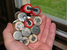 |
Battery rebuild |
Nice! But we still have a charger issue or two. First, I have
no charger for the Black & Decker style battery. Second, the
Ryobi battery was palpably warm after charging – it would
seem the charger isn’t controlling the charge rate as it
should. This might be because the cells were so worn out, or it
might be why the cells were so worn out.
Again I refer to James Wilf’s article at:
https://homepage.ntlworld.com/wilf.james/nicads.htm
He provides a design for a “dirty DC” charger. Here
is how I put it together for charging a 14.4 volt battery.
Cheap transformers
The transformer voltage needs to be 1.5-2 x the battery voltage.
In this case that means 22-30 volts. I’ll bet you don’t
have a transformer in that range laying around, do you? There
are a couple choices. One way is to gang together some unused
9v wall wart transformers like so:
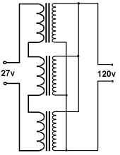 |
Gang transformers |
Most of these don’t handle much current, but this might
be OK for normal charge rate. The normal charge rate is 1/10 the
amp hour rating of the cells. Mine are 1200maH cells, so I need
to charge at 120 mA. A lot of wall warts will fall short but you
might find a few that can do the job. (At the fast charging rate
of 1200 mA, forget about it!)
The other problem is mounting them. Generally the diode is inside,
and you need to get rid of it to make the circuit above. After
cracking open the cases it takes a bit of engineering to invent
a way to fasten those little transformers to a baseplate –
they usually don’t have any screw holes!
I think it is a lot simpler to rewind one big transformer. Fortunately
you can get the raw materials dirt cheap. Microwave ovens are
a form of trash that most people have to pay to get taken away.
This makes it easy to get some free ones that are dead or simply
unwanted. Usually the transformer is still good in a dead oven.
(Be sure to also harvest the big magnet from the magnetron –
very handy for holding screwdrivers and chisels! Even hammers
– they’re quite powerful.)
| MOTs |
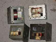 |
Microwave ovens transformers (MOTs to transformer hackers) are
designed to provide a constant current supply at very high voltage.
We don’t care so much about that, but it does make them
super easy to rewind – the primary and secondary windings
are completely separate! On normal transformers they are wound
in layers. An excellent article on rewinding can be found at:
https://www.users.on.net/~endsodds/psrewind.htm
So I’ll just cover what I did.
I had already removed the secondary windings (the one with the
finer wire) from some of these transformers, so the first step
is to figure out how many volts per turn it will generate. This
is easy. Wrap a single layer of scrap lampcord around the core
and measure the output voltage. (Actually, first wire a fuse into
the primary! Start with a small one, too. I don’t want to
belabor the point, but electricity can kill you, so be smart.)
 |
MOTs test |
With 9.59 volts and 8 turns, this one came out to 1.2 volts
per turn. So if I want 29 volts, I need 24 turns. These turns
can be made with any wire with insulation that can stand 50 volts
or so, and that has a big enough cross section to conduct 200
mA. But bigger is better, if you can fit it. I used 22 ga magnet
wire, mostly because I had some. Its maximum current rating is
1.28 amps, which is just barely beyond our maximum fast charge
rate of 1.2 amps. This is fine for me, since I only plan to charge
at the normal rate. You can see why given my history of cooking
batteries.
While you’re testing volts per turn, also measure length
of wire per turn. Most MOTs have the laminations welded together,
so you won’t be able to take the transformer apart and wind
the coil the easy way. Fortunately, with so few turns we can pre-measure
the wire needed (plus some extra!) and “sew” it through
the core. Be sure to wrap the core in electrical tape first to
protect the wire’s insulation from sharp edges, and be careful
not to kink the wire while feeding it through. It took me maybe
an hour to wind this one.
I guess I’d better explain how transformers work for those
who aren’t familiar with them.
How transformers work
If you go looking for articles online about how transformers
work you will find two main categories. The first is written by
engineers, for engineers. They go into detailed measurements and
complex math that we have no need to care about. The other category
or articles is by audiophiles/guitarists, who can go on for ages
about the sound quality of various output transformers. Again,
our needs are far, far more basic.
A transformer is like a gearbox. Imagine voltage as shaft rpm
and current as torque. To transfer a lot of torque a low rpm,
you need a huge, strong shaft. This is analogous to a fat wire
for high current and low voltage, like arc welding. Arc welding
is like driving in 4x4 low range, broken shafts and melted wires
(or welding rods) being analogous. To transfer the same amount
of power at high rpm, the torque will be lower and the shaft will
be smaller. Think of the tiny output shaft of a weed whacker powerhead
– very little torque needs to be transmitted because it
runs at like 7,000 rpms. This is also why we transmit power long
distance on “high tension” (high voltage) lines –
we need less metal to move the same amount of power. It is like
using higher rpm to reduce the torque.
When we need to change rpms, we use a gearbox or pulleys. The
small, fast shaft coming out of your motor gets geared down lower
to put the same power into a slower, fatter shaft that goes to
the wheels. This is exactly what a transformer does. The high
voltage from your wall socket can be stepped down (or up) to whatever
voltage you need.
But how?
The number of turns in the transformer’s primary winding
is analogous to the diameter of the driving pulley, and the number
of turns in the secondary is analogous to the diameter of the
driven pulley. Instead of gears meshing to transfer power, we
have a magnetic field vibrating back and forth.
By the way, that “back and forth” part is important
– this only works with alternating current. The magnetic
field can only induce a voltage in the secondary when the voltage
in the primary changes. Put direct current in and you create an
electromagnet, but no current is induced in the secondary.
Now when you’re done with this article, you should re-read
Max Wawrzyniak’s bit on how outboard ignitions work. It
will make a whole lot more sense now, since the magneto uses the
same electromagnetic principles, only with a moving permanent
magnet.
OK, back to Mr. Wilf’s charger.
Charger Details
We now have the transformer. I wound mine to 28.8 volts (24 turns)
with the idea of using an automotive 1157 bulb as the series resistor.
The “major” filament (the bright one) is around 6
ohms, and the minor filament is a bit under 24 ohms. For slow
charge I use two 1157s with all filaments in series to get about
60 ohms. Any one of these filaments could easily dissipate the
7.2 watts of heat we’re dealing with here, and in series
they all share it. We’ll be lucky if they even light up.
So how do we find out? First let’s “breadboard”
the circuit. If you ever hear electronics types talking about
“breadboarding” a circuit, this is where the term
came from. Back when men were men and components were enormous,
you could cobble your circuit together literally on a breadboard
before bothering to build an enclosure for it. Nowadays breadboards
are little things with sockets for integrated circuits and other
tiny components. Well, unless you’re me. Here’s the
circuit breadboarded.
| First charger |
 |
Those terminals are the same copper nails that are handy for
clench nailing the butt straps on instant boats. (This is all
I use them for now, since I’m pretty sure the Payson fiberglass
butt joint is a better way to go in every way.)
Notice the bulbs weren’t lit. This is true even when it’s
plugged in because there is nothing to draw current. I didn’t
want to hook it to the battery without some kind of test, however.
So let’s short the leads! This might sound reckless, but
it is a reasonable test, actually, since the bulbs are meant to
limit current and the battery cannot possibly draw more current
than this.
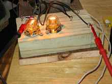 |
One filament |
Well, we can immediately see a problem. As I predicted above,
only one filament in each bulb is lighting up. That's a problem,
too, since the resistance changes as the filaments heat up, and
we're counting on the higher resistance of a red-hot filament.
Let’s get an idea how much current we’re actually
running here. To do this we measure the voltage drop across a
known resistance. The resistance of the bulbs is not exactly “known”,
since it changes so much with temperature. To get a better measurement,
I hooked an 8 ohm power resistor between the charging leads.
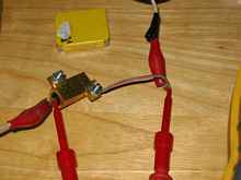 |
Resistance test |
The voltage dropped across this resistor was 5.056 volts. Ohm’s
Law says that volts / resistance = current, so 5.056 volts / 8
ohms = .632 amps. 632mA is far beyond the normal charge rate of
120mA.
OK, let's try a different bulb. A 194 is designed for .27 amps
at 14 volts, which should equate to 51.85 ohms. We're shooting
for 60 ohms, so this might put us in range. One problem is that
our voltage is higher than the bulb can tolerate, so we'd burn
them out pretty fast. If we put two in series, they can tolerate
twice the voltage, which should fix this problem. But this also
doubles the resistance to around 104 ohms, and we'll charge slower.
But we can put two of these pairs in parallel to cut the resistance
in half...back to the original 51.85 ohms!
| 194s |
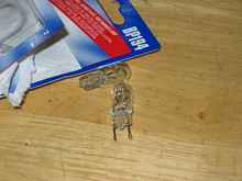 |
Another thing I like about the 194 is that one can easily unbend
the terminal wires and fasten them. They do not solder well at
all, but screw terminals would work fine. (I would literally just
use some screws.) They are also cheap at around $1.50 each, and
no need to buy a socket. Here's what it looks like with some bad
solder joints on copper nails.
 |
194 quartet |
The quartet of 194s tested at about 190mA, which is a bit quicker
than the rate I wanted for this battery, though probably still
reasonable. For a 1800mAh battery it would be perfect. For a 1200mAh
battery I'd rather back it down a bit, so I don't have to watch
it as closely (You already read how well I do in that situation.)
We can do this in one of two ways. Either we can run only one
pair of 194s to cut the current in half, or we can peel a few
turns off the transformer. Removing two bulbs is easiest, so let's
try that first.
I also removed the shunt resistor because this dirty DC makes
my meter's display jump all over. It seems to do it a tiny bit
less without the shunt for some reason. The proper tool would
be a vacuum tube voltmeter with its nice, smooth analog action,
but mine is currently out of commission, I'm afraid. It’s
on a long list of winter projects.
Anyway, with two 194 lamps, I again clipped in the 8 ohm resistor
and measured a 1.08 volt drop across it. I also measured an 11.31
volt drop across the pair of lamps. This tells us something extremely
useful. Here it is graphically first...
| Lamp resistance |
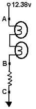
|
Again our friend Dr. Ohm tells us that because we have 1.08
volts dropped across 8 ohms, 0.135 amps must be flowing. (That’s
point B to point C above.) The same amount of current must be
flowing through the pair of 194 lamps, since they are in series
in the same circuit. Since they are dropping 11.31 volts (point
A to point B above) and we know 0.135 amps are flowing, we can
deduce that their combined resistance when heated is 83.78 ohms.
This is very handy, since we can't measure that resistance directly
very easily while power is running through them.
135mA is pretty reasonable for this battery, but here's the truly
cool part: now that we know the effective resistance of the lamps,
we can measure the current flowing into the battery whenever we
like! For example, with the battery almost fully charged, the
lights get dim. Only 3.75 volts is being dropped across the lamps.
If they are still 83.78 ohms, the charging current is 4.47 mA.
(Though when they get very dim, I suspect the resistance starts
to drop. An experiment with a different larger value fixed resistor
could confirm this.)
To finish the charger I added back the 1800 ohm shunt resistor.
Also note that I have to point a fan at the charger when it's
running. Even though we are underusing the potential power of
the MOT, it still heats up without a cooling fan. The diode is
a 1N5404, which can handle a full 3 amps. Mr. Wilf recommends
over-rating the diode by a factor of 5-10, so a 3-amp diode is
a bit of overkill, but for 7 cents why not?
Polarity
I’m sure you noticed my barely-labeled leads. It is of
course critical that you hook them up the right way, but there
is actually no need for a label. With no power connected, hook
the leads up. If the bulbs light up from the battery’s power,
the leads are backwards. Reverse them and charge. I intentionally
do this every time to make sure I have them on correctly before
plugging the charger in.
Smart charger tricks
While taking apart these batteries I noticed a few things. The
Ryobi batteries have temperature sensors taped to one of the cells.
When the sensor starts to heat up, the charger shuts down to prevent
boiling away the electrolyte. Clever. Except it doesn’t
do as much good if the cell with the sensor happens to be one
of the stronger cells. A weaker cell could be overheating and
the charger would never know. Still, one sensor is better than
none. Since the Ryobi cells are all weak and I have the official
charger, I guess I’ll rely on that for now. But I did keep
the sensor from the dead pack. This might play into future plans
for smarter charging.
The Black & Decker has no temperature sensor at all. This
was a bit surprising, since I generally think of Ryobi as the
very bottom of the market, unless we count the thoroughly useless
Chinese-made store brands like Tool Shop. However Black &
Decker does have a sort of a sensor – they add an extra
wire from between cells 6 and 7. This allows the charger to test
each half the battery separately. I assume that it compares them,
and if the difference is too great it decides that a cell is dead
and refuses to charge. It’s pretty simple to apply this
without the “official” charger. Every few charges
I test both sides of the B&D battery, just to see if a cell
is on its way out.
Save the orphans – mains power for cordless tools
So how about that Ryobi drill with the dying battery? For that
matter, I also had a Skil that was missing any kind of battery.
OK, so we have a couple good drills with no power supply, and
a half-dead power supply (the battery charger) of about the right
voltage.
Paging Dr. Frankenstein…
Actually, we’d better first page Dr. Ohm and figure out
if this is likely to work.
Theoretically this car charger can produce 6 amps at 12 volts.
This seems like a reasonable draw for a drill motor, so let’s
try it. I hooked up the power to the drill with jumpers. Sure
enough, it runs! But the ammeter buries on start-up and whenever
the motor slows almost to a stop under load. And I mean it buries!
I could hear the needle click against its stop at the extreme
top of its travel. Next stop after a huge current draw is normally
a melted transformer, so started thinking of ways to limit current.
Current Limiting Strategies
The three main ways of limiting current are a fuse, a resistor
or a non-linear device.
A fuse is simple – it is just an intentionally thin spot
in the wire that heats up and burns out before everything else.
It also doesn't waste any power before it blows, which makes it
a winner for common circuit protection. However, when these drill
motors hang up, they draw a lot of current. Almost like a dead
short. This means blowing a fuse for almost every screw you put
in. That's no good here.
The resistor is simple too, but we are limited by the linear
reaction of the resistor. We would prefer something that increases
in resistance as more current flows. Well, as it turns out we
already looked at a non-linear device.
A lightbulb goes on
Yup, back to bulbs. For the same reason it is a pain to measure
the resistance of a bulb, it is great for limiting current. Its
resistance increases with temperature. More current = more heat
= more resistance = less current.
Just make sure it is in series with the load, not parallel as
it would commonly be wired. Wire it like a fuse – if you
unscrew the bulb, the power should turn off.
This seems like a very low-tech solution, but actually it’s
not. This strategy was used in the Wien bridge oscillators that
first put Mr. Hewlett and Mr. Packard on the map. You can find
bulbs protecting treble drivers in some rather nice sound reinforcement
equipment as well.
The trick is getting the right size.
Right-sizing
Fortunately the engineering involved is very basic. Above we
mentioned that the charger can produce 6 amps at 12 volts. Multiply
the two numbers together to get 72 watts. A 72 watt lightbulb
should limit the current to about what the transformer can handle.
Let’s play it a little safer, however, and go with a 100
watt bulb.
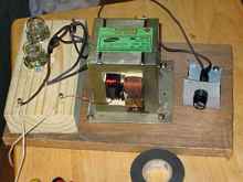
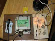
In this setup, a 100-watt bulb lights up dimly when the drill
is not in use.
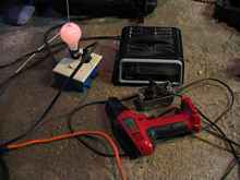 |
Drill rigs |
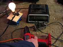
When I pull the trigger it light brightly, then drops down to
a moderate level. This is because the motor is only drawing a
moderate amount of current. If I grab the chuck and stop the drill,
the motor draws its maximum, and the bulb lights brightly. But
the needle on the ammeter never buries itself. Perfect!
Almost.
Or maybe not...
This concept of the current limiting transformer got me thinking
– why didn't the mains fuse blow when I stopped the drill
and the ammeter needle buried? Clearly it wasn’t drawing
all that much current on the primary side of the transformer.
Furthermore, I could hold it that way for some time without smelling
windings burning, even without the lightbulb in series!
Let's have a closer look. All we need is a cast off lamp cord
with banana plugs soldered to the ends, so we can plug it into
a multi-tester.
First the secondary (the drill side). When I'm not pulling the
trigger at all the voltage is 14.21 volts. (Well look at that—I
guess it somehow fixed itself! I believe the patient is having
second thoughts.) Turning the drill on with no load drops the
voltage to 9.85, and the bulb lights up moderately. A lot of that
voltage is probably getting dropped across the bulb. Forcibly
stopping the drill drops the voltage to 1.28 volts. It is also
easier than it should be to stop the drill. Let's take away the
springboard effect of the bulb.
Now choking the drill drops our DC voltage to 4.53, and the drill
still generates enough torque to chap my hands. So now let's check
the mains voltage side of the equation. My voltage at the end
of the extension cord is 117.3, which is not particularly great.
But forcibly stopping the drill only takes it down to 114.8.
To truly figure out what’s going on, I’d need to
add a fixed resistor to the mains side and measure current. But
even intuitively we can guess that the transformer is the limiting
factor here – there’s a lot more voltage drop under
load on the secondary than the primary. To me this means that
the transformer is saturating – it’s magnetism is
working as hard as it possibly can – before the full magnitude
of the short can be applied to the primary.
Why bother?
Part of the reason I bothered with this is the hand-operated
chucks on cordless drills. These are much quicker and more convenient
for bit changes. Another is the clutch, which makes it a lot quicker
and easier to drive screws just the right amount. Another reason
is this approach made use of several orphaned tools. It is nice
to be able to set them up with separate bits for a project and
plug them into the same power supply.
Of course this setup has some limitations. I’m depending
on a transformer that apparently suffers from mood swings, for
one.
Of course I could always wind something with one of my spare
MOTs.
Rob Rohde-Szudy
Mazomanie, Wisconsin, USA
robrohdeszudy@yahoo.com
*****

|