While perusing a website I ran across a chart plotter computer that had the computer attached to the back of the screen, it was either a Nano or Pico Mother board and it was very compact, and very expensive, basically just a screen. I said to myself “I can do that” and it turns out I was right. This article is not for a zero experience computer person. If you don't know what a standard ATX power connector is or IDE, IDE 40 pin cable, if an IDE Compact flash adapter sounds like jargon maybe you should just read this for fun. None of this is rocket science. Basic PC computer layouts and ports haven't really changed much in 15 years, but if you haven't opened one up and messed around then you should probably not start this project until you get a little more knowledge. It is possible you could fry a monitor following these instructions For those who are the real experts I have no problems with corrections, I am just a putterer
My goals were
- 12 volt power, I wanted a simple system that would plug into the boats 12 volt system, no little inverter needed like if you were running a laptop. (I know-- there are 12V power supplies for laptops and I have been using them)
- Minimal space, I wanted just the screen base and screen.
- Minimum 12” screen 15” preferable.
- Cheap--modern big screen chart plotters tend to be in the over $4,000 range, I wanted to get in for less than $500.
- Touchscreen if possible, I have been spoiled by using an Itronix laptop.
It is intended for inside use, aiming at power boat application but could be used at a sailboat nav station. It is not waterproof in any way.
Operating system
I decided to use Windows 2000, its stable and still supported. I would have preferred to go with Linux because of min cost but there are no good nav programs in Linux, or at least I have never got one to run well and be usable easily. My nav program of choice is the free SeaClear With free charts for the US from Noaa.
Motherboard
I decided that if I was going to stay cheap I would not go to a Pico or Nano board, they are really small but tend to run in the $250-300 range or more. I just arbitrarily went to the cheapest miniITX board at minibox the Intel D945GCLF, first time I have used an Intel board in years. One of the fanless Via boards would certainly be more elegant and less tall, as well as more expensive. I also got the 1 gig of memory (who can resist a gig of memory for $19) and the really neat small and efficient DC DC power supply.
This power supply operates on an input of 12-25 volts so you can plug it into an AC DC supply while getting it to work before you take it to the boat. It is a lot more than the motherboard requires so you can use it to power the monitor. In addition I got a Y cord so that I could split the power off the power supply and I got an IDE Compact flash adapter (female)and a 4 Gig compact flash card. To act as a Hard drive. You could use a 2.5 “ HD, not too expensive and easy to find mounting rails. I wanted max simplicity and min power draw.
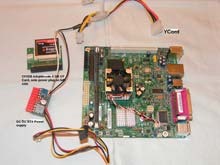 |
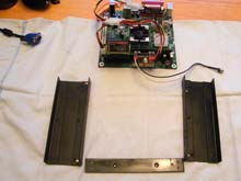
So here is a pic of the basic parts of the computer
click images to enlarge |
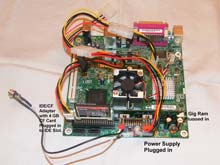 |
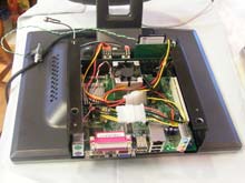
Here is the the Motherboard with basic parts plugged in. The Y cord allows you to have a spare 12/5 volt IDE power supply. With this Intel board you have to have an extra power input for the Chip which is what one leg of the Y cord is going to. The power for the CF card is off of the end of the Power line, it used to be used to power Floppy discs in the past. |
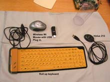 |
Now we have a pic of the accessories, the plastic container is for the roll up keyboard. The GPS is a Holux 213, they are getting harder to find. Any USB GPS would work Garmin makes the GPS 18, De Lorme makes one for their street atlas that I know some use. If possible get one with the Sirf III chip it is very sensitive. |
OK next you need a monitor, now the main purpose of this exercise for me was to have a totally DC powered system. As far as I know (remember I am just an amateur) all of your flat screen LCD monitors are DC powered. Now you may see that AC power cord going into the back and want to disagree but my understanding is that it hooks into a power supply that puts out DC for the monitor. It used to be that the LCD monitors all had a power brick that plugged in to AC and provided the DC power for the monitor but that brick is incorporated into the monitor now. I was fortunate to have a 15” monitor sitting around that had a brick so I used that. I was prepared to by a small monitor-17” maximum and go into the back to bypass the power supply. This will violate the warranty of course and very well may trash the monitor. My brick put out 5 volts and 12 volts according to the label. When I cut the cord and tried to figure out which wire did what I was very disappointed because the voltage readings were not 5 and 12 until I figured out that the shielding cable was the ground. The ATX power supply puts out 5 and 12 volts, 5 volts on the red and 12 on the yellow black is ground of course. As a side note DC ground on the latest boat wiring standards is yellow.
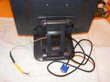 |
So on this next picture a female plug bought from a local computer store is wired in to the wire that use to go to the brick - Red to the 5 volt wire and Yellow to the 12. If you are going into the back of a monitor then you will have to use your volt meter to figure out what is the output from the power supply in there and wire accordingly. Finding this out is the trickiest part of what I am proposing and the greatest opportunity to do damage to yourself or the monitor. On the back of the monitor are two mounting holes into which I have inserted two screws, This is where I will mount the computer. |
So next is mounting the computer to the monitor. I made a couple of sides out of angle aluminum and very lightweight sheet aluminum. The stand offs to keep the motherboard from resting on the frame are standard. I had a bunch I am sure any computer store has them. I drilled and tapped the angle aluminum for the threaded standoffs using the motherboard for proper hole spacing, I did this before attaching the sides. You have to have the standoffs to keep the motherboard from shorting out on the aluminum To get the position right on the cross brace I attached the angles to the mother board, then figured out where two holes in the end of the cross brace would hit the angle pieces, drilled the holes in the cross brace and matched them up with the two angle pieces and marked where the holes should go. Make sure the bottom of the computer is going to clear the mount on the monitor when it is all assembled. I them assembled the sides, drilled holes that would allow me to screw the computer to the standoffs. After painting I screwed in the standoffs with epoxy on the threads so they wouldn't back out (my tapping job was shaky).
 |
I attached the motherboard to the sides. I then riveted the cross brace on with 1/8th aluminum pop rivets, same as I use to attach the sides to the angle aluminum. I then removed the motherboard and mounted the case on the monitor, you can't get to the mounting screws with the motherboard in the way. I used blue loctite on the mounting screws and on the screws attaching the motherboard to the frame when I reattached it. |
 |
Here is the monitor face down with the Computer on the back, no back to the case yet. The little green and white wire is to a push button hooked to the on off jumpers on the motherboard. Forgot to show that earlier. |
Programming
Loading the OS should actually be done before you assemble it or even make the case. No use wasting all that effort if you need to take it apart or if you fry something. You can start out with the motherboard just siting there. I used a standard HP 19 volt AC laptop adapter to power it with. The DC DC power supply can handle 12-25 volts. I found I could not figure out how to load off a USB jump drive so I ended up using another monitor to free the IDE power and then plugged in a 40 pin IDE cable, got another IDE/CF adapter with male instead of a female end and plugged in the slave end to a CD Rom player (don't forget to set it to Slave). I then turned it on with a win2k disk and it booted and started loading on the CF card. Once I had win2k loaded and all the compatible drivers off of the Intel site. The drivers were a whole separate issue, it turns out this board is for XP only so I have a few issues with win2K the worst being getting the USB ports to work well with modern Jumpdrives. I set it back up with the CF card mounted as shown. I then hooked up the LCD modem and and whoopy do it all worked. The wireless Wi USB plug in blocks the USB ports from anything else but the thinest USB in put. I have found that I have to use a wired mouse if I am going to use a jumpdrive to load any other stuff. The Holux or a Garmin18 will both fit into along side the Wi though its tight. Once everything is loaded you can unplug the keyboard and roll it up and store it. The only wire out of the whole set up is the power supply and the wire to the GPS.
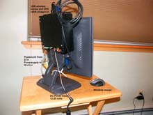 |
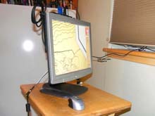
So here is the finished product, |
 |
If I and when I put it on a boat it will probably be a larger cruising power boat and I will screw it down through the plastic with washers. Thanks to already having the monitor I have about $270 invested. |
***** |