|
Part 1 - Part 2 - Part 3
Being addicted to boatbuilding can be a problem. You may acquire more boats than you have time or space for. Even for simple boats, the outlay can be a considerable dent on the domestic budget. And while your spouse may love sailing as much as you do and appreciate the grains, textures, and fine workings of wood, she may get tired of sawdust wafting in the air and being tracked in the house.
 |
Being addicted to boatbuilding can be a problem. An ideal solution is to find a friend who wants a boat, and then help him or her build it.
click images to enlarge |
An ideal solution is to find a friend who wants a boat, and then help him or her build it. And that’s how it worked out for me recently when our friends, Olivier and Tiffany, decided they wanted to add a small sailboat to their "fleet" of two small kayaks. This arrangement had considerable advantages:
• Someone else is paying for the bills.
• By sharing tools, Olivier saves some money.
• I get to go over, make some sawdust, slop some epoxy around, and then go home at the end of the day.
• It’s fun sharing knowledge acquired from past projects with a first-time builder, as well as learning some new nuances from a different design and some ideas from an insightful builder, even on his first project. (Olivier is an architect by trade, and was constantly applying lessons from that craft to the art of boatbuilding.)
• Bits and pieces of materials and gear that I was unlikely to use found a home on Olivier’s project, reducing the clutter at our home.
Olivier is French, and has grown up sailing small boats in France, but hasn’t sailed for years. He wanted a design that would be performance oriented, but not excessively demanding. He had seen the balanced lugs on my Jim Michalak Piccup and Frolic2 designs (as well as had sailed on the Frolic2), and favored that rig.
He settled on Michael Storer’s Goat Island Skiff, which has the balanced lug rig but is tilted towards a performance orientation. Also, Olivier, despite my reassurances about its building ease, had misgivings about tack-and-tape construction and liked the hard-chine style of the skiff. For my part, I had built a couple of hard chined boats before, but both had external chine logs; so the internal logs of the GIS would be a new twist.
In January, Olivier acquired the plans and an epoxy kit from Duckworks, some beautiful Meranti quarter-inch marine ply, and cedar, pine and spruce lumber from a local yard. We were off. (Storer recommends Okoume ply for lighter weight, but the difference in using the Meranti is less than the difference between Olivier and me in weight (I’m the heavier one) and we liked the extra rot resistance and strength of the Meranti. The significantly less expensive price for the high quality ply was also a factor.)
Here’s a summary, with a time estimate, of how the building process went. The time is a rough estimate. Omitted is time for meals and just standing around looking at plans or the boat.
Session 1:
Lay out and cut all bulkheads and transom. Lay out the paper patterns for the sides, trace, cut out, and use as pattern to make the second side. Butt strap the side panels together to make the two sides. Time: about 5 hours
 |
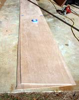
 As an architect, Olivier had access to a large CAD printer and so printed full size patterns of the sides. Those had to be cut with scissors and then carefully laid out and scribed on the plywood. We’’‘re not sure that saved any time over the more traditional laying out and drawing the lines with a batten, but it proved extremely accurate. As an architect, Olivier had access to a large CAD printer and so printed full size patterns of the sides. Those had to be cut with scissors and then carefully laid out and scribed on the plywood. We’’‘re not sure that saved any time over the more traditional laying out and drawing the lines with a batten, but it proved extremely accurate. |
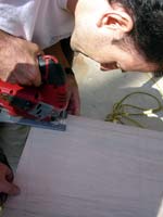
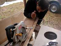
| Olivier makes the first cuts with a jigsaw. Later we went to a circular saw with the blade set just keep enough to go through the ply and found that faster, just as accurate and with smoother curves. |
 |
 |
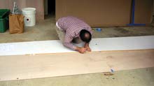
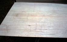
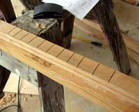
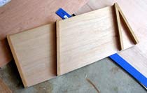
The first side, after cutting, is laid on the ply as the pattern for the second side panel. |
| It may be a little hard to see, but here are some of the penciled drawings for cutting out the transom and bulkheads. |
 |
| At the end of the first day, we had the sides assembled and glued and a the transom and a pile of bulkheads. Not bad for the first day!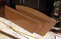 |
 |
Session 2:
Rip cedar into proper size pieces for the chines and the bulkhead framing. Measure, cut and glue most of the bulkhead and transom framing, allowing overlaps of the framing for beveling. Glue on the internal chine. Time: about 5 hours.
|
|
| A lot of ripping of timber during this session and then cutting it and fitting for framing of the bulkheads. |
Session 3:
Plane and sand the bevels into the bulkhead framing and finish gluing the transom and bulkhead framing. Lay out, saw, chisel, & sand the variable-bevel stem. Cut the chine notches into the bottom corners of most of the bulkheads. Time: about 5 hours.
 |
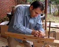
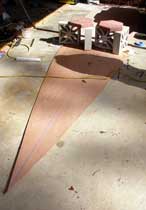
Possibly the trickiest part to make was the stem, which has a variable thickness and bevel for its entire length. We laminated a piece up to the maximum thickness, and then drew the stem full size.
Saw cuts were made down almost to the penciled lines, which allowed most of the excess wood to be chiseled off. Planes, surforms, and sanders did the rest of the shaping work.
Olivier, shown with the surform, proved to have a real flair for work like this. Total time to make the stem: about two man-hours. |
 |
|
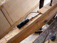
 Olivier cuts an access hole, which will be covered with a deckplate, that will allow access to the watertight storage under the stern seat. The framing has been attached, but not notched for the chine, which proved to be a moderately fussy job. About this time, Olivier got a Japanese pull saw, which made such fine work easier. Also, designer Storer does not give the bevel angles for the framing; instead he specifies an overlap distance which is planed to make the correct bevel. This worked okay, but I have a personal preference for having the angles which then can be precut into the framing with a circular saw. Olivier cuts an access hole, which will be covered with a deckplate, that will allow access to the watertight storage under the stern seat. The framing has been attached, but not notched for the chine, which proved to be a moderately fussy job. About this time, Olivier got a Japanese pull saw, which made such fine work easier. Also, designer Storer does not give the bevel angles for the framing; instead he specifies an overlap distance which is planed to make the correct bevel. This worked okay, but I have a personal preference for having the angles which then can be precut into the framing with a circular saw. |
In between, sessions 3 and 4, Olivier removes screws from the framing and chines, begins filling the screw holes with thickened epoxy, and cuts the last chine notches in the bulkheads. He also cuts the limber holes in the middle two bulkheads.
Session 4:
Attach the sides to the stem with screws only, and then dry fit the sides around the bulkheads and transom. Remove one by one, add thickened epoxy to the hull side and bulkheads and reattach. Use a trailer tie down strap with ratchet as a Spanish windlass to hold the ends when gluing the transom and stem. Fill any gaps by the bevels not being precise with thickened epoxy. Measure, cut out, and laminate the daggerboard, adding carbon fiber between the ply layers. Time: about 6 hours.
 |
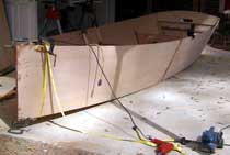
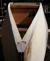
The sides are temporarily fit to the stem and the forward two bulkheads as the boat begins to take shape. There’s a slight curve to the sides of the forward bulkheads and frames that slightly tortures the ply panels, adding both strength and difficulty in getting the bulkheads and panels aligned. It wasn’t too hard with two of us, but a singlehanded builder would need a spanish windlass and persistence. As a bonus, the torturing add a subtle and lovely twist to the bow. |
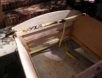
| The transom is added. We found that the racheting tie down straps available inexpensively at boat and hardware stores make an excellent and easy to use Spanish windlass. Here it holds the transom in place for a trial fitting. |
 |
 |
The bulkheads were removed one by one and reinstalled with glue. Here’s the finished result, with the ratcheting strap making easy work of getting the bow sections wrapped around the bulkheads and the stem. Suddenly, it looks like a boat! |
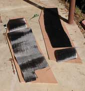 Designer Storer gives three options for the centerboard. Once is to use an old Laser board (and the mast and sail instead of the designed balanced lug). A second option is to laminate timber strips, which are planed to the designed thickness and then shaped into the centerboard. The third is to laminate plywood. Storer feels that the plywood version isn’t as strong as the timber strips, and so recommends a shorter board. I happened to have some scrap carbon fiber, nearly as thick as normal fiberglass woven roving. We decided to laminate that between plywood layers and make it the full length of the strip version. With the carbon reinforcing, we’ll tolerate no complaints about board strength! There’s enough scrap ply to get the three board layers from the six sheets specified to building materials. The catch is then there’s not quite enough to make the athwartship seat in the center of the boat. We got around that by butting two scraps together, lengthwise, and putting a layer of fiberglass tape on each side to get a piece big enough for the seat. It shows no weaknesses along the butt. Designer Storer gives three options for the centerboard. Once is to use an old Laser board (and the mast and sail instead of the designed balanced lug). A second option is to laminate timber strips, which are planed to the designed thickness and then shaped into the centerboard. The third is to laminate plywood. Storer feels that the plywood version isn’t as strong as the timber strips, and so recommends a shorter board. I happened to have some scrap carbon fiber, nearly as thick as normal fiberglass woven roving. We decided to laminate that between plywood layers and make it the full length of the strip version. With the carbon reinforcing, we’ll tolerate no complaints about board strength! There’s enough scrap ply to get the three board layers from the six sheets specified to building materials. The catch is then there’s not quite enough to make the athwartship seat in the center of the boat. We got around that by butting two scraps together, lengthwise, and putting a layer of fiberglass tape on each side to get a piece big enough for the seat. It shows no weaknesses along the butt. |
Session 5:
Layout (from paper templates) bottom panels, check on hull for fit. Bevel chines and frames. Remove screws used to attach bulkheads, stem and transom. Cut bottom panels, leaving slightly oversized, and glue on butt straps. Measure and cut centerboard case sides, cut and glue on most of internal and external case framing. Time: About 6 hours.
 |
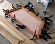
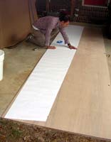
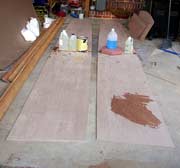
The bottom panel was roughly laid out and then placed on the bottom for final measuring, and then cut oversize. Here weights hold the butt straps in place while the epoxy sets. There’s a gap in the straps along the centerline where the centerboard case will go, and along the panel edges to allow for the chine logs. |
| The chines are fitted to extend beyond the bottom of the boat, so they can be planed flat before the bottom is attached. Here’s a view from the bow as the beveling is proceeding. |
 |
 |
The framing on the bulkheads also extends below the bottom and must be beveled. Some of the as yet unfilled screw holes can be seen in the side panel. |
 Framing is cut and sized for the centerboard case. Storer does not recommend fiberglassing the inside section of the case, but does recommend three coats of epoxy, allowing each coat to begin to harden before applying the next one. The coating was actually done in the next session and we also added graphite powder to the last coat, to increase abrasion resistance. The case was clamped together after the third coat was applied. Framing is cut and sized for the centerboard case. Storer does not recommend fiberglassing the inside section of the case, but does recommend three coats of epoxy, allowing each coat to begin to harden before applying the next one. The coating was actually done in the next session and we also added graphite powder to the last coat, to increase abrasion resistance. The case was clamped together after the third coat was applied. |
In between: fill screw holes, some sanding
Session 6:
attach bottom with thickened epoxy and temporary screws after marking bulkhead locations and drilling pilot holes for screws to bulkheads. Apply three coats of epoxy to inside of centerboard case, the last with graphite powder, and then glue the case together. Time: 3 hours.
Yes, there should be some pictures here, but someone forgot the camera that day . . .
In between, remove screws, trim & round bottom edges, fill screw holes
Session 7:
Cut and install framing for fore and aft decking, including center supports and gussets. Mark slot for centerboard on bottom. Time: 5 hours.
 |
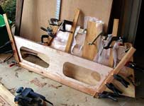
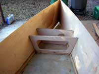
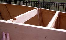
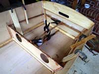 The framing and gusset supports for the bow and stern seating/decks are installed, using scrap timber to extend the reach of the clamps. I was worried that the 1x1 framing (red cedar) seemed a little on the light side, but so far it has seem plenty strong enough in practice. Note how the triangular shaped ply gussets are used where two frames intersect. The framing and gusset supports for the bow and stern seating/decks are installed, using scrap timber to extend the reach of the clamps. I was worried that the 1x1 framing (red cedar) seemed a little on the light side, but so far it has seem plenty strong enough in practice. Note how the triangular shaped ply gussets are used where two frames intersect. |
In between, remove clamps from fore and aft deck framing, cut and begin shaping for final fit of foredeck. Time, four hours.
Gary Blankenship
On to Part 2...
***** |