| Last
time I finally figured out a remote steering
system that would work well in a small light sailboat,
for anyone fool enough to insist on one. Like me.
Here’s how I installed the whole mess.
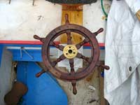
Mounting the Wheel
The nicest installation would have been running the
wheel’s shaft right down into the compartment.
Unfortunately that would have put the wheel where
it would interfere with the mast. I wanted at least
3” clearance to decrease the likelihood of smashing
the steering wheel when stepping the mast. So I stood
the shaft off from the bulkhead, using an exposed
cable drum.
The lower bearing is simply scrap wood nailed and
glued to the bottom of the boat. The lower layer is
a 3x5” square piece of ¾” plywood,
and the upper part is a 3.5” length of 2x4.
The upper part is bored to 1-3/8” with a hole
saw. The bearing fits in this hole. Cut it so the
fit is snug. Make sure this wood assembly gets attached
so it centers the shaft on the boat’s centerline.
This could be done without the bottom piece of plywood,
but I didn’t want the shaft to jab into the
boat’s bottom if something broke. Probably paranoia,
but it’s cheap insurance.
Note how I cut limbers to allow the escape of
any water that dribbles down the shaft.
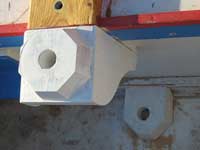
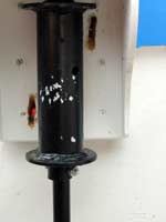
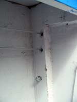
The upper bearing block is built like a mast partner.
I added one extra bearing to have bearings top and
bottom on this block. That way the setscrew on the
drum locks the shaft in place, so it isn’t actually
riding on the bottom of the lower bearing block –
it’s floating above the bottom. That bearing
only keeps it centered against the cable tension.
So the upper bearing block is made from a piece of
2x6 nail-and-glued to ¼” plywood sides
and a 1x6 back, through-bolted to the bulkhead with
plenty of PL400. Make sure you’re bolting to
something substantial.
Note the limbers on the bottom of the lower block.
These allow drainage of any water that finds its way
down the shaft and through the bearing,
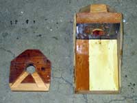
As you can see, my boring wasn’t 100% accurate.
(In fact it wasn’t even close!)
No big deal – as long as the top looks OK and
the bottom keeps the bearing from getting shoved into
the block too far. A bit of rasping in the lower hole
of the upper bearing block made it work well enough.
As long as there’s a little wood left to support
the upper block’s lower bearing it is good enough.
I switched to steel cable to minimize play in the
system, but cable shouldn’t be bent into a circle
less than 2” diameter. In fact, the Duckworks
sheaves I was using were 2.5”.
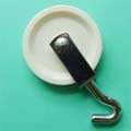
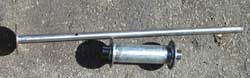
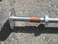
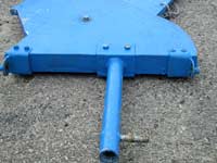
So I had replace my 1.5” wooden drum. While
wood would have worked fine, I couldn’t find
a 2” diameter dowel. This one was welded from
1.5” iron plumbing pipe, which has an outside
diameter of very close to 2”. I welded on 3”
flanges and collars of ¾” pipe. The shaft
is ¾” mild steel rod welded to a 3”
disk of 3/16” steel.
Right now some of you are about to tune out because
welding is required. It’s not really required.
You could do this stuff with hardwood without too
much trouble. It was just faster to do it with welding
because I’m equipped to weld. Besides, if you
prepare the metal, this would be a very cheap welding
job to hire. Any farmer or mechanic with an old “buzz
box” could zap this together.
The shaft is installed with a collar made of ¾”
copper pipe to lift the wheel above the level of the
upper bearing block. This keeps fingers from getting
whacked on the deck when spinning the wheel fast.
(Why copper? For the best of all reasons – I
had some laying around.)
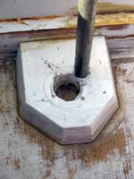
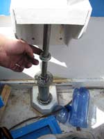
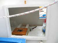
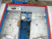
At this point I test fit everything and bored the
drum and shaft to pin them. Here you see the middle
bearing and the drum, both lower than their final
locations.
The drum has to be pinned in place on the shaft right
under the middle bearing, because the drum is what
holds that bearing into its block. So we hold it all
in place and drill. Make sure the bottom end of the
shaft is suspended above the bottom of the boat, but
is deep enough into the lower bearing block to be
supported by the lower bearing. With the shaft forced
down and the drum holding the middle bearing in place,
drill the hole. Actually, I drilled the hole in the
collar of the drum before starting this. Then I drilled
the shaft just enough to make a mark when holding
this all in place. It was much easier to finish boring
the shaft with better lubrication where it wouldn’t
move around or make such a mess – in a vice.
I used a ¼” bolt for the pin. Be sure
the hole isn’t oversized or the steering will
have excess play.
All these parts got washed with Spic-n-Span, rinsed,
dried and primed with Rustoleum Bare Metal Primer.
If you use the brush-on type, you will probably need
to apply this as you install the parts. You might
not be able to slide the bearings onto the shaft with
a thick coating of dried paint. But it would probably
be OK with the spray version. I hate spraying paint,
though, and have the feeling that a thick coating
is good on a boat. Here is the shaft assembly installed.
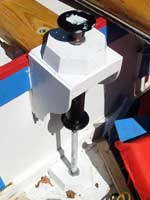
And finally notice how I cut slots rather than holes
for the cables. As they roll onto and off off the
drum, their angle changes. So you need a slot instead
of a hole to avoid rubbing.
Meanwhile, back at the rudder…
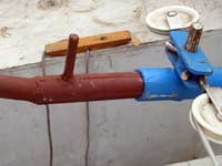
The wooden tiller from the previous effort rapidly
showed itself to be far too weak. It snapped like
a matchstick! Probably bad wood, but I made a much
stronger one from steel plumbing pipe.
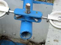
Note how the yoke fits over the pin on the tiller?
This allows easy removal of the rudder for transport.
A word to the wise – 1/2” steel rod usually
fits nicely into 3/8” plumbing pipe.
I should mention that there’s another way to
do this. I’m not sure which is better, but I
think the above version can take more strain. But
if you’re using Dacron line in place of steel
cable, this one certainly works fine.
And you don’t really need to use steel cable
unless you’re…
Steering the Motor
Since we're discussing the rear end of the steering
system, let me save you some time. If you have a rudder
anyhow, don’t bother rigging steering for the
motor. The rudder will do fine. In really close quarters
you can always grab the motor’s tiller.
There’s another benefit to this approach too.
Using the rudder, the steering is much more stable
than with the motor alone. You can leave the helm
for some time and it will track straight. With motor
steering you really can’t leave the helm at
all. Trust me, I tried.
OK, time to run cables.
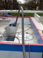
Cable Runs
This is a particular challenge in this case. The
simple approach would be to run the cables along the
side, then bring them straight across the bulkhead
to the drum. But I have hatches in the way, and I
do actually need them. If I had run the cable outside
the center compartment, I would have needed some awkward
45 degree sheave mountings to keep the cable away
from the port hatch cover. So I decided it was better
to run the cable inside the compartment, only having
it come out to meet the drum. This required running
all the cables down the port side to avoid the daggerboard
case. By keeping the top of the drum high up, I got
away with only six sheaves total inside the compartment.
As you might imagine, this was a huge pain the butt
to work on through 12” square hatches.
I seriously considered cutting them larger, but managed
to do it without. Suffice it to say that you’re
far better off doing this kind of thing before the
decks are on. (Or using a tiller…)
Here’s a trick, though. With a 12” hatch,
you only ever have one hand to work with unless the
compartment is very shallow. Thus it is almost impossible
to mark hole locations by holding a piece of hardware
in place and marking the holes (with the other hand).
I got around this by marking the holes on paper, then
sticking the paper to the bulkhead with double-stick
tape. A punch awl provides centers to drill on, and
drilling can be done (if awkwardly) with one hand.
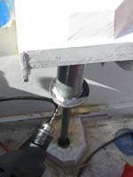
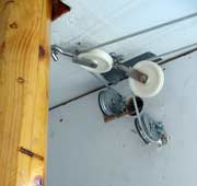
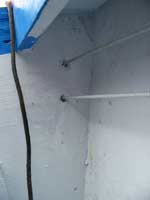
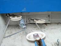
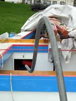
As the cables come through the bulkhead from the
drum, a 90 degree block turns the lower one up to
the bottom of the deck. From here, a pair of blocks
turn the cables to the port side of the hull. This
photo shows both.
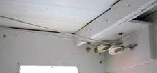
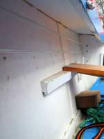
There, another pair turn them aft to the holes in
the bulkhead, under the side deck. Each time you make
a turn, you need to hold all the blocks in place with
the cable under tension to make sure the cable ends
at the right spot without rubbing on anything. Including
the other part of the cable! And be sure to have your
masts stepped when doing this if there is any chance
at all they could interfere! Here are the blocks that
turn the
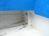
The same is, of course, true of the underdeck cables
and getting them to the motor well bulkhead. Running
the cable through the motor well bulkhead is fairly
simple, but remember that the locations of these holes
will determine the locations of the next set of sheaves
or holes if you are to avoid rubbing the cable against
things.
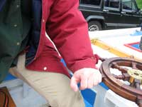
Then the cables run to the tiller steering mechanism.
The extra pad eyes are from an attempt at steering
the motor. Like I said before, don’t bother.
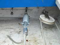
The springs are set to about 50 lbs of tension, and
the cables clamped. These springs then absorb any
unevenness in the system and help keep it under tension
at all times. It is easy to stab yourself in the hand
with a screwdriver while tensioning these springs,
so be careful.
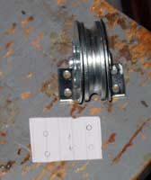
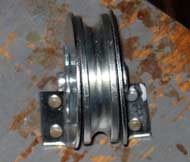
Special Blocks
You’ll notice that this system requires a lot
of sheaves. On the other hand it does work pretty
well, and Duckworks helps keep the cost under control.
But we need a special fitting. Steering sheaves are
made for where the cable is pulling away from the
anchor point. But the way my wheel is set up, I need
the opposite kind to take cable off the drum without
it rubbing in the hole through the bulkhead. These
are readily available at decent hardware stores and
agricultural suppliers. I got these at Farm &
Fleet for about $4 each. That’s a little pricier
than I would have guessed, but to get 2” sheaves
you’re stuck with a weight rating that is radical
overkill for a boat this size.
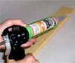
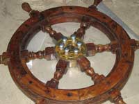
Stiffening the Rickety Wheel
I finally came to realize I was never going to make
time to build my own wooden steering wheel. So I resigned
myself to stiffening my junky Ebay wheel. To do this
I removed the wheel and wrapped the bolts in lots
of plastic packing tape. Then I mixed some epoxy and
added thickener to get something about like mayonnaise
or a little thinner. I put the taped bolts in place
and removed them one by one as I pumped in epoxy with
a large veterinary syringe. This epoxy goo oozed out
the cracks where the wood spokes joined the “tin
can” hub. With all the bolts back in place I
placed packing tape over the oozing cracks to press
the goo as flat as possible. Finally I flipped the
works over so the bolt heads would hold the epoxy
in, and shot a little more into the bolt holes on
the bottom.
Then I hung a 100 watt light as close as I could
and started checking frequently. When the epoxy reached
the rubbery stage it was time to act again. I could
tell because I could still make an indentation with
my thumbnail, but it wasn’t easy. The easier
way to tell is that the leftover epoxy is no longer
try to sag. It is solid, but still a bit soft.
At this point I pulled off the tape and removed the
bolts. I had pull them with a prybar and block, but
they came out without too much protest. Epoxy is pretty
easy to scrape off in this soft state. I should have
waxed the metal and spokes by rubbing with a candle.
Then no epoxy would have stuck to them. I forgot,
so rather more scraping and polishing was needed than
I had hoped. Then I refinished the entire wheel with
thinned boiled linseed oil. It is more stable than
before, but still not what I’d call ideal.
But wheels aren’t everything.
Emergency tiller
This system has a lot of moving parts that could
break. When motoring one can always grab its tiller.
But we are not always motoring, so we need a backup
for steering the rudder. (Especially with complicated
sail rig and a motor that needs to be “romanced”
into action!)
This is no mean feat, since the tiller has to reach
up over the motor. It has to lock in place so it can’t
turn in its socket, yet be very fast to install.
I made the tiller socket from 3/4” steel pipe
with a slot cut to mate with the stub tiller’s
internal weld seam. This keeps it from turning. I
had to sand down the ¾” pipe to get it
to slip inside the tiller’s 1.25” pipe.
Then I welded on some ½” steel pipe and
bent it to clear the motor. The motor isn’t
present in the photos, but believe me, it really does
take up that much space!
In case it tried to slip out of place in rough water,
I provided a vertical pin that could be lashed to
the yoke pin on the stub tiller. This would force
them together. Note that I haven’t tested this,
however.
Nobody wants to hold onto a steel tiller very long,
so I will eventually finish it with some twine lacing
like on my oar handles. Or maybe I won’t. It’s
just for emergencies, after all.
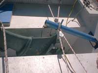
It lays flat on the bottom and ties to a screweye
on the chine. Reasonably out of the way, but enough
in the way to remind me that wheel steering isn’t
ideal on a small boat.
Like all the modifications I have made on this boat,
this wheel steering business suggests that a different
design would have been a better fit for me. Live and
learn.
Rob Rohde-Szudy
Madison, Wisconsin, USA
robrohdeszudy@yahoo.com

Click
Here for Other Articles by Rob Rohde-Szudy |