Part One - Part Two - Part Three
Last 'Where to Build' article I detailed my requirements for a site to build my boat and looked at the options for a weather proof covering to protect the work from the elements and provide a comfortable working environment. This second article covers the design and construction of the boat shed. In order to follow the description in some places you may find it necessary to refer to the pictures.
So as usual let’s start with some requirements.
- To allow sufficient space to work round the 24’ x 8’ boat I recon the shed would need to be about 32’ x 14’ this leaves 3’ either side, 2’ at the front (enough to walk round the stem with the doors closed and 6’ at the rear to allow for material storage or a bench.
- To make a rigid structure two rows of posts will be needed about 14’ apart with gaps of 4’ between the posts, giving 9 posts on each side.
- A double sloped roof needs tie beams to prevent the roof collapsing and forcing the walls apart, these should be sufficiently high to provide working space and sufficiently low to hold the rafters in place.
- A ridge pole will be needed to hold the trusses in place, provide rigidity and support the polythene.
- Cross bracing will be needed on the roof to give the structure more rigidity.
- Ventilation will be required but must not let rain in.
- Full width doors at the front will allow access for the trailer and provide extra ventilation in hot sun (if we ever get any).
- A smaller door would be convenient for continual access.
The first job is to measure up and site the shed (I use the term shed loosely as it has more in common with a polytunnel). Having done this the corner posts need to be planted, I used the 3-4-5 triangle method to get the corners square and placed bamboo canes at the corners as temporary markers. All post holes were dug approximately 18” deep to take 9’ x 3” x 3” posts. To facilitate easy removal at a later stage I filled round the posts with stone chippings and for the top 3” placed a mixture of chipping and Postcrete (a quick setting concrete which sets in about 5 minutes).
|
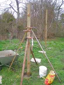
A handy way of holding the post in place before the rafter support is added |
Once the corner posts are in place and the cement set, two strings can be placed along each side to line up the position of the middle posts. As I was doing the job entirely by myself 4 clamps and props were used to hold the posts in place prior to fixing them. Once a couple of mid posts had been planted the rafter support could be screwed along the length of the shed on the inside and remaining posts then screwed to this to hold them in place while the holes were filled.
|
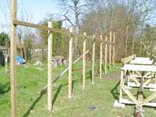
At last some progress is made with the first line of posts in place |
As you will notice from the photographs the site was on a slight slope, I decided to have a step aft of the boat transom to prevent a muddy job of removing a lot of soil and having to exhume our two cats who died a couple of years ago
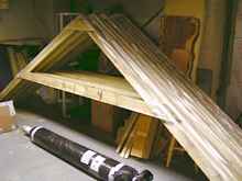
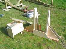
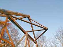
The roof trusses could be assembled in the garage I made one of the correct size and then placed this on the floor as a template, laying the timbers of subsequent ones on top to get exactly the same size and shape. Because the roof was designed to take a very light load (i.e. not tiles or slates) there was no need to have a king post and side struts. Timber connectors were used to hold the tie beam in place and the joint firmly bolted. Once all the roof components were made polythene was stapled over the top to prevent the rough timber chafing the outer cover and wearing a hole.
|
Roof trusses made and waiting in the garage. Coach bolts and timber connectors were used for the joints. The rafters are covered with a strip of polythene to prevent chaffing the roof sheeting |
Now comes the most difficult job of the lot, holding a 14’ truss 7’ above the ground while adjusting its location and making a permanent fix. Fortunately with a little forethought and a few clamps the job becomes do-able, I would never say it was easy, and a few unmentionable words were muttered. Here is the sequence of events:
- Line up the ladder between the two posts the truss will be attached to, in a position suitable to rest the truss against
- Lift one end of the truss and place it on the rafter support
- Clamp the truss to the post above the rafter support, but not too tightly
- Climb up the ladder and lift the other end above the opposite rafter support
- Lean the top of the truss against the ladder, ease the clamp and slide the truss so that an equal amount hangs over each rafter support
- Clamp both sides of the truss to the posts
- Mark both sided where a cut will be made so the rafter sits square on the support
- Undo one side clamp and slide the truss up and to the centre to gain access for the cut
- Cut the small triangle out and set the truss in place
- Do the same on the other side
- Drill and bolt both sides of the truss to the posts, use penny washers to spread the load
The difficult part was getting the truss in place, once this was done the rest was easy.
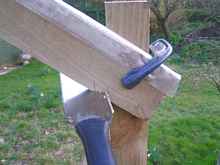
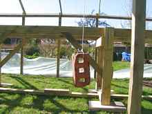
|
My handy helper ready to be assembled. If you don’t know what it is see the picture further down. |
|
Cutting a notch in the rafter for it to sit firmly on the support. |
I converted my aluminium extension ladder to a free standing ladder several months ago in preparation for this task with bolt on top and feet. The top is constructed with a tray for tools and screws, which proved very handy. The ladder proved itself to be essential and very stable. I could comfortably sit on the top without fear of it overbalancing even though some of the ground was uneven.
|
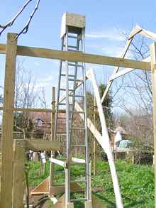
Placing the roof trusses could not have been done without the ladder. |
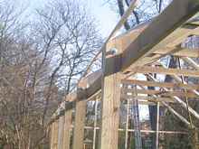
Once the roof was bolted in place the ridge pole needed to be screwed in place. I measured the distance between subsequent rafters on each side and averaged this distance for the spacing at the ridge. Even taking great care to place the poles in exactly the right place there was still an inch or sometimes two, discrepancy between one end and the other. At this point the structure was still a bit wobbly and needed to be stiffened up so some cross bracing was applied. I was surprised how much difference these small flimsy pieces of timber made to the overall stiffness.
|
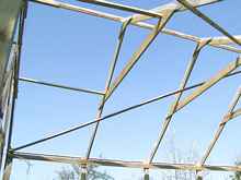
The cross bracing made all the difference. I added a couple of extra pieces at the ends to hold the middle of the end rafter. |
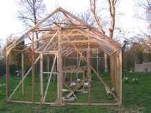
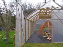
Beginning to take shape, but still a way to go. Next is the ventilation as I had natural triangles at the ends between the apex and the tie beams, which would be above the height of the door all that was needed was to provide some form of shield to prevent rain being driven inside by the wind and a fan could also be mounted up here later if forced ventilation was required.
|
I hope the end apexes will supply enough fresh air and let out the heat in summer. |
The door was an easy design, two half doors to open up the entire end of the structure up to the tie beam, it would need a brace to prevent sagging and some form of holding the brace in place over the long distance. I decided to put a small door in one side as this would be far more convenient to use and would be in use most of the time. The main doors would be opened on warm days for extra ventilation and obviously to allow the trailer to be wheeled in when it was needed. The other end consisted of a few laths of timber attached to stakes at the bottom end, just sufficient to hold the covering in place, I was thinking of leaving the covering loose to allow it to be rolled up when required.
|
The end doors took a morning to make, and that included cutting the wood. |
|
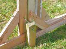
The mechanism for holding the doors closed does not have to be sophisticated.
I placed a cross piece on the door stop to support the doors and prevent sagging over time. |
At this point a design defect became apparent at the post rafter junction, this would be an area where the polythene covering was under pressure at corners, I felt that it should have more support and so fitted a small rib of wood along this junction to ease the stress points, a bit like a chine of a boat in structure. It needed to be smoothed and rounded with a plane.
|
Even though this timber is less than an inch square it supports the polythene very well. |
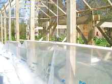
Finally the structure was built and it was time to apply the covering and flooring. The covering I was assured was a two man job, or in my case one man plus ingenuity. I always say there is nothing that can’t be done with a few bits of string some timber and several bricks with holes. In this case 3 bricks with 3 holes each.
|
Polythene raising mechanism. |
|
Trusty helper on the other side of the string. |
The process was going very well until I read the label on the outside of the polythene sheet which said “THIS SIDE ON THE INSIDE”. Even so ten minutes later I was back at the same place having turned the sheeting round.
The only jobs left were to secure the bottom edge of the covering, which was wrapped round a long piece of timber and screwed to the posts, and fit the flooring of a non slip weed suppression mat, held in place with six inch wire staples.
I am very happy with the way the shed has come together, it took 71 hours at a cost of £343 , but most of the materials will be reused when the structure is taken down. After I have used it for a while I will write another article giving an evaluation of its performance.
*****
Click HERE for a list of articles by Mike Machnicki
|