
 Custom Search
|
| boat plans |
| canoe/kayak |
| electrical |
| epoxy/supplies |
| fasteners |
| gear |
| gift certificates |
| hardware |
| hatches/deckplates |
| media |
| paint/varnish |
| rope/line |
| rowing/sculling |
| sailmaking |
| sails |
| tools |
| join |
| home |
| indexes |
| classifieds |
| calendar |
| archives |
| about |
| links |
| Join Duckworks Get free newsletter CLICK HERE |
|
|
| How to Create a 3D model from an Old Paper Plan |
by Jacques Mertens – Vero Beach, Florida – USA |
Part One - Part TwoOr Lofting on the Computer - Part One
|
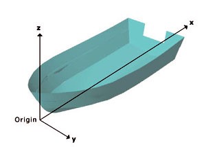
The design we will use in our example is not a free plan. It is an Atkins design named Shoreliner.
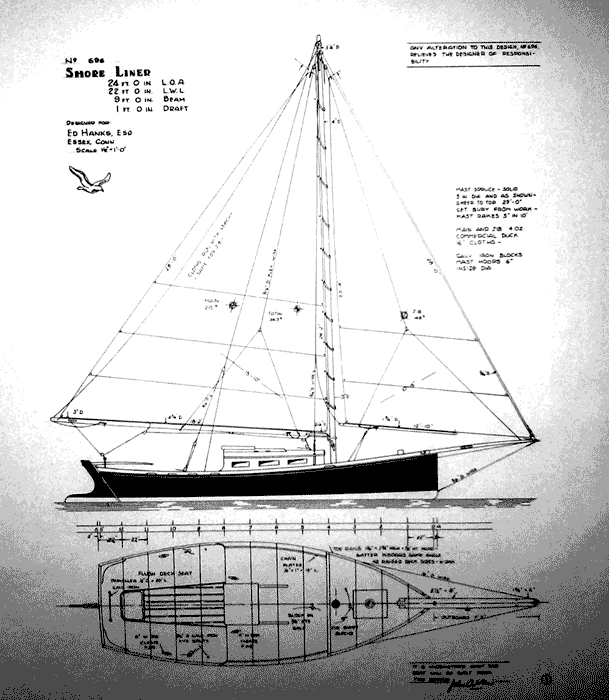 |
The story behind this project is simple: after building a pontoon catamaran from one of our bateau.com CNC kits, Hugh T. wanted to use the same technique and material to build that Atkins design.
He commissioned our office to design and produce a CNC kit for the Atkins Shoreliner.
This involved 3 steps:
- Create a 3D model of the hull (= lofting);
- Extract plywood panel and other part dimensions from that model;
- Calculate new weights and scantlings.
In this file, we will cover the first part: enter the lines in a 3D modeler. We will call that procedure 3D lofting.
Lofting means redrawing hull lines from plans full size and correct inaccuracies resulting from the scaling (fairing).
Lines drafted on paper can only be as accurate as the thickness of a pencil line and this easily becomes 1” when scaled. Add some drafting variations and we quickly have the accuracy reduced to several inches. More about that later.
Part of the lofting job is also to insure that the different 2D views match each other and produce fair curves in 3 dimensions.
We will redraw the hull full size on the computer instead of drawing on the shop floor.
The software we use is named Rhino3D.
Rhino with Orca has become the industry standard for yacht design. Our office uses it since 25+ years but our method can be used with any 3D modeler including open source (free) software like Delft.
Reading the Plans
Designers don't want you to measure from the drawings. They show dimensions for the hull lines in what is called a “table of offsets”.
That table shows the position of points on the hull in 3 dimensions.
They want you to draw those lines full size and take all dimensions from that full size drawing (= the lofting).
To draw the hull, we will enter all the table of offsets points in our computer software and join them by lines or by a surface.
The Atkins Shoreliner is a hard chine hull, flat bottom and the hull is defined by two lines, chine and sheer. It is a simple hull but the technique is the same for a complex round chine hull.
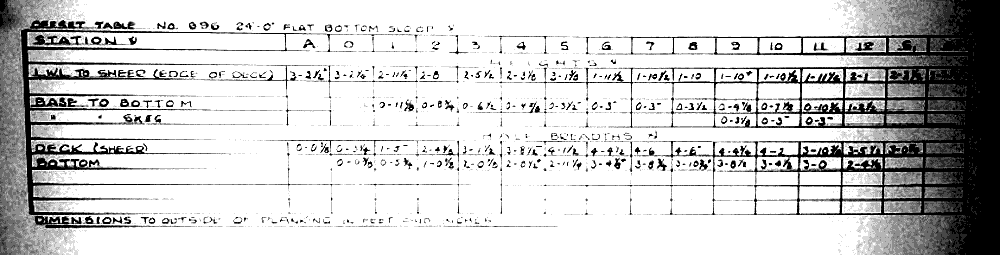 |
Picture above shows the table of offsets.
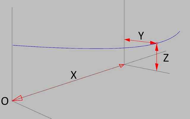
Coordinate System
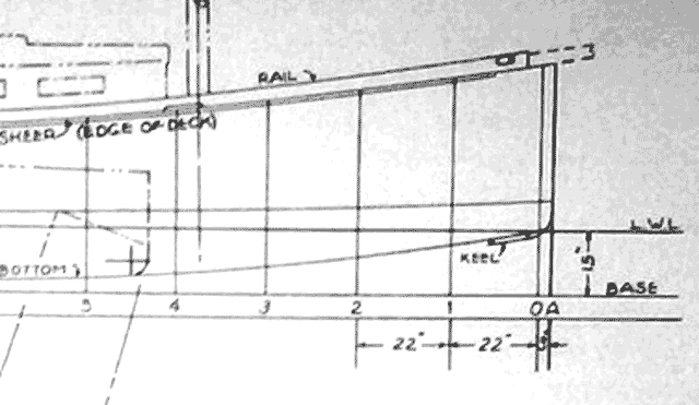
Working on the computer in 3D, we use the coordinates: X, Y and Z. See the picture below.
 |
Each point on the hull is defined by 3 dimensions.
In boat design terms:
X is the stations location, measured lengthwise along the waterline.
Y is the width, the beam of the boat at that point. (half breadth)
Z is the height, above or below the waterline or baseline.
Heights can be tricky, not all designers measure from the baseline. In the case of the Atkins plans, height is sometimes measured heights from the LWL to the sheer or from the Base (baseline) to the bottom. Read carefully.
How to Read the Dimensions
We will find all those dimensions in the table of offsets but the table uses unusual units.
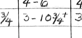 |
For example, the last row on station 8 shows 3-10-3/4+.
The 1st number is feet, the second inches followed by fractions up to 1/8” and, if needed, a plus or minus sign.
3-10-3/4+ means 3' plus 10” plus 3/4” plus 1/16”.
The plus or minus equals 1/16 but in the mind of the drafter, probably means “a little bit more or less”.
We will overlook the plus or minus. We must fair anyway and you will understand why later.
We use engineering units.
Engineering units means all dimensions in inches decimal. This makes math much easier and reduces the risk of errors.
That 3-10-3/4 is (36+10+0.75) equals 46.75” in engineering units. Much easier to read and that is what you will enter on your keyboard anyway.
It's easy and fast once you get used to it (and metric is even easier).
Entering Points in 3 Dimensions
We will draw points in 3 dimensions then join the points at the chine and sheer.
(If this was a round chine hull, we would enter many more points and join them by a surface).
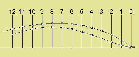
This picture shows lines through points in plan view with marks at each station.
 |
In our example, we decide that the origin from which we locate all points is at the intersection of station 0 and the baseline (BL).
We are going to be consistent and measure all height (z) from the same origin.
Let's draw the points at station 8.
First, we must locate station 8 along the X axis.
Atkins show all stations equally spaced by 22” except for the ones at the ends, transom and stem.
Let's draw a line at each station to keep things clear.
That puts station 8 at 8*22 = 176”.
Our X coordinate for all points on station 8 will be 176.
Let's mark a point on the sheer, at station 8:
We need a height (Z) and a width (Y).
 |
Station 8 is shown in the table of offsets as a column.
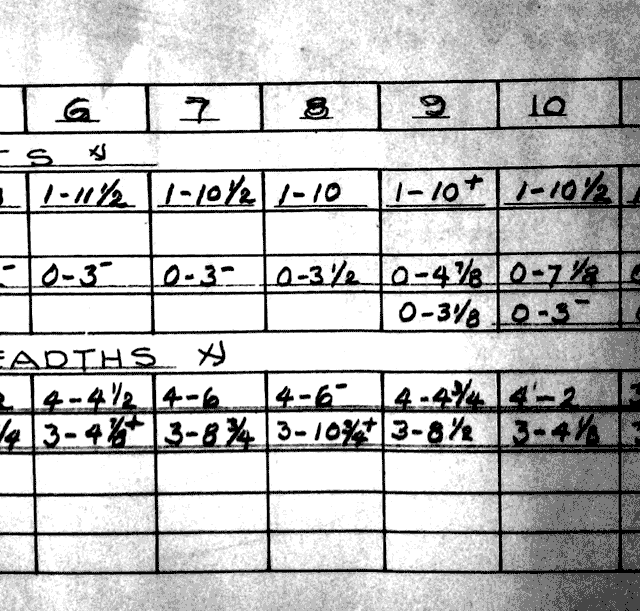 |
First the height (Z).
The 1st row of that column is named “heights” LWL to sheer. This is the height at the sheer, above the LWL.
It is marked 1-10 (22”) BUT it is measured from the LWL.
The LWL is 15” above the BL (see the plans) and we will adjust the heights from LWL, in this case, add 15”. This means, height above BL = 22+15 = 37”.
Z = 37.
Yes, Atkins moves his coordinates, get used to it! He uses the LWL for the sheer height then decides to use the baseline for the chine.
 |
Next, we need the half beam or Y.
The table shows the “half breadths” for the sheer, as 4-6.
In engineering units: 48+6 = 54”.
Y = 54.
Let's enter the points of station 8 in the modeler.
We will use keyboard entry in x-y-z.
172,54,37.
(No decimals in this case).
All 3D modelers will let you enter 3D coordinates as above but you can also draw the points graphically.
Let's draw another point, the chine at station 8.
Height: table shows 0-3-1/2 (note the leading zero)
Z = 0' 3-1/2” = 3.5
This time Atkins measures height from the baseline!
Width: 3-10-3/4+.
Y = 36” +10-3/4 = 46.75
In XYZ: 172,46.75,3.5.
Now we have the two points that define the hull at station 8.
Let's create the points for all the stations, one by one and join the points by a curve, one for the chine and one for the sheer.
Those lines have kinks resulting from the scaling imprecision. We must fair the lines.
Most 3D modelers have fairing tools, use them and try to stay as close as possible to the original points.
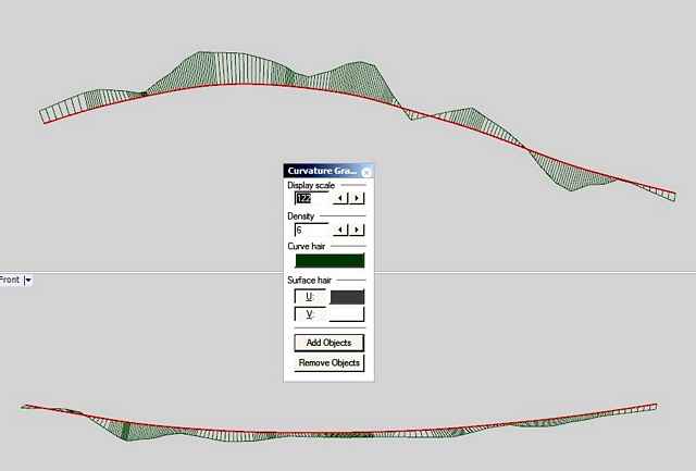 |
This is a picture of the chine in plan and profile view, created directly from the table of offsets but with some points corrected because of flagrant deviations. The curve graph shows how unfair the curve is without editing.
We can create and fair the lines in 3D but there is a better method.
This is the same curve graph, same line, exact same analysis settings but faired with the method we use. We will describe that method below.
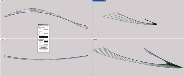 |
See how smooth the curve looks in all views.
To comment on Duckworks articles, please visit one of the following:
|


 |