| To Part
One
Before installing the deck, I figured out where we’d want
to attach hardware. On the aftdeck, we’d have two pulleys
for the steering and two attachment points for some sort of traveler.
I’ve heard a traveler is sometimes called a horse, and the
coincidence amuses me that General Robert E. Lee’s horse
was named Traveler.
On the foredeck, we’d have three pulleys for the steering
(more on this later), some bracing for the (two) mast partners
(remember those two mast steps down in the bilge?), a mooring
bit, maybe some cleats and some anchor line chocks. A little overkill
on a boat this size.
Underneath these designated areas, I attached some plywood squares
and a short plank of 1x6 to screw things into. I forgot to tell
you the deck is ¼” plywood. I think screws would
pull out of that faster than, well, faster than cracked corn through
a goose.
The deck is in four pieces. Five, actually, but that’s
because I pieced the foredeck together from two pieces to use
up two smaller scraps I had. There are two narrow side decks about
4” wide, one aftdeck over the lazarette, and the foredeck
covers the first two sections. They were attached by screws put
in at a slight angle to grip the ¾ gunwale strips better.
The entire surface was fiberglassed.
 |
Dry run. Christer Bystrom's Stella Class KADET |
Fore and aft decks are slightly curved, side to side. My son
and I tried to bend the rear deck by soaking it, suspending it
between two sawhorses and loading some really heavy rocks on its
unsupported center. I don’t think my wife noticed we borrowed
anything from her garden border.
After a few days we concluded that was not too successful a
method, so I resorted to cutting shallow kerfs on the backside
of the plywood decks, and they curved satisfactorily.
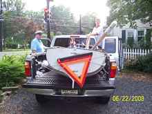 |
Driveway- stern. Loaded and ready to head to
the water. |
Coaming consists of planks made from 3/8 plywood. The side coaming
is attached with little blocks of wood. The coaming strips are
about three inches high, but only about 1 1/2” projects
above the deck. Of course, there was some tracing involved to
make sure the curve of the coaming matched the curve of the deck.
I screwed the blocks of scrap wood under the deck and screwed
the coaming to those blocks. Forward, the side-to-side coaming
is simply screwed to the frame. (* A note here – the centerboard
adapter slides up and hits this slight projection, so you might
consider your options here.) There’s no coaming at the aft
of the cockpit, but that was just a matter of personal esthetics.
I notice Christer didn’t put coaming at the aft of his cockpit
either, but he does have a vertical lip at the sheer. That is,
his deck appears to be inside the hull, my deck rests ON the hull
and projects about ½“ past the side of the hull.
All the coaming was coated and sealed with fiberglass and resin
at the same time as the deck to make a solid, uninterrupted connection
to the deck.
There is a jam cleat on each side coaming for the jib sheets.
The rudder is two side pieces sandwiching a kick-up lower half.
Christer says he occasionally encounters submerged rocks. I usually
encounter the beach. The “official” design of the
lower half is a straight blade with parallel fore and aft edges,
but I like the trailing edge curved, so curved it is. Greg Wadsworth,
for whom hull #2 was drawn, also re-drew a curved-end rudder to
get a bigger blade. I planed and sanded the trailing edge thinner,
because I think that looks swifter.
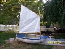
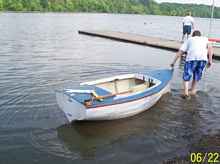 |
Walking to dock. First time in the water. Lake
Carnegie, Princeton, NJ. |
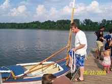 |
Ready to board. Mast stepped, spars attached,
rigging on. |
Since the rudder is directly behind the captain, and the boat
doesn’t really have a lot of space for sitting sideways,
the steering is designed to be via a rope. (My brother tells me
there are no ropes on a boat, only lines and sheets.) Christer
runs a rope around the outside of the cockpit, through pulleys,
and ties them to the short tiller. Pulling the rope this way or
that turns the tiller.
.jpg) |
Tyvek Sail |
.jpg) |
Tiller |
On Christer’s web site he has a lot of pictures of Queen
Mabs congregating in Boston. They use a variety of steering arrangements
that I considered. The rope and a push-pull tiller (through what
is called a “bell crank”) arrangement are the usual.
I toyed with the idea of a foot bar, like on a sled. I really
like that idea, but the space is limited and I didn’t want
to futz around with figuring out the physics.
I had been stewing in my mind about how my son would handle the
jib sheets and the steering rope and not confuse them, when I
had an inspiration. I could install a normal tiller, handy to
the captain’s right hand, so the captain could steer in
a perfectly normal fashion. The steering tiller will be parallel
to the rudder tiller and will pivot on a pin about an inch ahead
of the transom. There will be a link from the fore end of the
rudder tiller to the steering tiller, meeting the steering tiller
about an inch ahead of where it attaches on the rudder tiller.
That is, the link will not be an absolute right angle to the tillers.
Hopefully, that link will be parallel to an imaginary line from
rudder pintle to the steering tiller pivot pin.
Have I lost you yet?
That’s a parallelogram. Do you remember parallelograms
from school days? This should serve the purpose of keeping the
steering tiller parallel to the rudder tiller, so the captain
can steer using the tiller in the normal fashion, and the rudder
will respond exactly as if it were attached directly to the steering
tiller.
The only drawback I could see was that the tiller is ALWAYS
in the captain’s right hand, no matter what tack the boat
was on. Not too awful in a boat this small.
Painting was the next task. What is there to say about painting
that you don’t already know? Sand, sand, sand, paint, paint,
paint. The hull is two coats of white, the deck is blue, the coaming,
in and out, is white, the bilge and interior is cream/ivory/almond/ecru/beige/whatever,
the edge of the deck is red. I could make the hull smoother with
some more fairing mix (microballoons in resin), but I was more
anxious to complete the task than s-m-o-o-t-h the hull, and my
son says the irregular surface is OK with him. Floorboards are
white, with some red or green trim to identify port and starboard
placement. Rudder and tiller are white. The spars are varnished
with the ends painted white in the traditional fashion.
However, while I was painting the inside of the bilge, an idea
sprang to my mind. I could attach hinges to the frame at the front
of the centerboard trunk, one on each side, pointing up, like
two automobile accelerator pedals. At the tops, I could attach
lines running back, maybe under the deck, to the tiller. When
one pedal is depressed, the rudder turns, and the other pedal
rises.
I like that idea because it frees up the captain’s hands
for more important things, like paddling when the wind dies.
The more I thought about it, the better I liked it, so I decided
to go with that plan.
Now the steering ropes run from the tiller to small nylon pulleys
(window replacement hardware) at the far sides of the aft deck,
forward to eyes at the back corners of the cockpit, thence, through
eyes under the side deck, to the front of the cockpit, through
more window pulleys to window pulleys above the pedals, then down
to the pedals. The pedals are upside-down “L” shaped
PVC pipes with the leg of the L facing forward. The L is necessary
so the pedals can travel back into the cockpit (remember one goes
up when the other goes down) without the end of the rope hitting
the final pulley.
The system works, but with more friction resistance than I’d
like. Over Easter Break my son examined the foot-pedal steering.
His assessment was, “Coool!”
.jpg) |
Checking sail |
Cool it was indeed, but when we gave it a dry run, the combined
resistant was too much and one of the pulleys broke out, so it
was back to the parallelogram. For what it’s worth, I also
noticed my son had to scoot forward a little to reach the steering
pedals. Varying leg lengths is a consideration if you want to
try this route.
Now if only I could get an inspiration for the centerboard. I
like that it pivots, but the thing is spec’d out at 30 pounds!
That’s a lot of weight to lift up when sitting in a boat!
The board is designed to be made of steel. I think Christer has
a block and tackle to the mast head, but I’d like to think
of something easier. And maybe with less rope. (Christer admits
he has a lot of lines to keep track of.)
Christer and I discussed using sand-filled PVC pipes in the
bilge for ballast. I might try that so I can lighten the centerboard.
The pipes of ballast would be easy to remove.
I saw the article about using bungee cords to retract daggerboards
and rudders when sailing into obstructions, and I’ve been
mulling over a combination of the ideas.
My son and I made the sails from Tyvek, carpet tape and my grommet
kit. We could go the super-cheap route and scrounge for old sheets,
but we located a source that had Tyvek without the huge DuPont
logo and decided to spring for the $20. We tried them on for size.
They’re OK, but the mainsail could be a bit bigger. Or I
could make shorter spars. Or I could have measured better. Originally
we laced and tied the sails on, but I find that it is a real pain
to put the sails on and take them off, so I’m switching
to clips tied onto the spars. I did that on my catboat, too, contrary
to the designer and builder’s instructions. I don’t
leave my sails on the boat, so attaching and detaching them via
two dozen knots is cumbersome at best.
Christer’s plan calls for making the centerboard of sheets
of steel plate. I am not a metal worker, nor do I know any, so
I made the centerboard of plywood. I bought a 1” thick barbell
weight that seemed hefty enough, and cut out a hole that size
out of the lower part of the board. I also cut out two 3/8”
pieces of plywood the outside shape of the lower end of the centerboard,
with that same hole cut in the center. I put the weight into the
middle, covered the weight in fiberglass cloth, resined it and
put the 3/8” thick piece over that, and fiberglassed the
exterior again. Before doing the fiberglass mummification on the
other side, I filled all the spaces in the weight with lead shot
fishing weights.
Both sides of the rest of the board will be fiberglassed to
make it stiffer and stronger.
.jpg) |
Checking for leaks |
I’ll check its weight. I think it’s around fifteen
pounds, about half the specified weight. We’ll try that
for a while. I think my son will be able to lift it out of the
case without needing a block and tackle assist.
The centerboard adapter case was fairly straightforward construction,
once I thought through the purpose and figured out the positioning
of all the pieces. I did have to do some careful measuring as
the sides of the centerboard trunk in the hull were not quite
parallel. I simply made the adapter case to fit.
I nailed the pieces into place with short nails peened over
on the outside. The insides were well coated with resin, and perhaps
should have been painted, before the case was assembled for eternity.
Ditto the outside, but that could be done later.
Now all the pieces are made; they fit together, school is out
for the summer, so it’s off to Lake Carnegie for the sea
trials. The lesson is : You can make a boat with stuff you already
have in the garage and go sailing without making a big dent in
your budget.
By the way, I was going to paint the name "KADET" on
the transom,
but didn't get to that yet. (Swedish for 'cadet.' My son, Max,
is a
cadet at Carson Long Military Institute in Pennsylvania.)

|