- What Worked for Me
Last fall, I acquired a 30-year-old, glass reinforced plastic
(GRP) 4.5 meter sailboat. I observed that the EPS foam-chip-filled
flotation bags in the side tanks were starting to fail. I decided
to remove them and fill the side tanks with 2-part, 2 lb/cubic
foot foam expanding polyurethane foam per U.S. Coast Guard specifications.
After some thought, I realized that obtaining a good foam pour
would require cutting holes in on the upper surface of the side
tanks, that hardened foam could be excavated out from under the
holes for storage and that the holes could be covered with hatchplates.
I also observed that the two original forward 6 inch diameter
hatchplates were failing and needed to be replaced.
I located the six hatchplates (three per side) for adding foam
at the ends of the thwarts and near the stern to facilitate installation
and be somewhat out of the way. The holes were centered between
the thwart and gunnels. Rather than wrestle with a jig saw or
router in a confined area, I purchased a 4.5 inch hole saw to
ensure accurate hole cutting. I chose 4 inch plates (4.5 inch
holes) instead of larger plates to minimize any reduction in strength
of the surrounding GRP. Larger hatchplates, however, would have
been handier for storage.
After hole cutting, I inserted a hatch plate and outlined its
perimeter with a pencil to guide GRP cleaning and masking tape
application. I reinserted the flange, carefully scored the tape
around its perimeter with a shop knife, and removed the tape under
the flange (Figure 1).
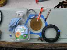
| Figure 1. A hatch plate opening, cleaned, masked
and ready for the silicon sealer and hatch plate. |
 |
I applied small tabs of masking tape to cover the screw holes
on the hatch plate bottoms (facilitated cleanliness and drilling
holes), applied silicon adhesive (per Chuck’s recommendation)
to the flanges and pressed each, with its plate, into place. Each
was rotated slightly back and forth to ensure good adhesive contact
with the GRP. I used clear “hardware store” silicon
sealer. I considered stronger adhesives, but concluded that the
lower cost silicon was adequate and would remove more easily if
the hatchplate needed replacing.
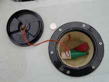 |
Figure 2. A completed hatchplate and cavity.
I carved the foam cavities before installing the hatchplates.
The foam carved easily, especially with a serrated knife.
In retrospect, it would have been better to have excavated
larger cavities before setting the hatchplates. I attached
the plates to the flanges using light line connecting 12 gauge
copper electrical wire loops glued to the plate underside
and into the foam with 5-minute epoxy. |
To complete the installation (Figure 2), I scored the hardened
silicon around the hatchplate’s perimeter with the shop
knife and peeled off the squeeze-out and underlying masking tape.
The hatchplate holes guided the drilling for ¾ inch #8
stainless flathead screws. Using a bit the size of the hatchplate
hole, I dimpled the GRP for centering the subsequent 1/8 inch
bit. The screw threads were coated with silicon sealer before
installation.
For the forward hatchplates, each hole needed to be slightly
enlarged. I used a router guided by a template secured to the
GRP with two countersunk flathead screws. These two holes matched
opposing holes in the hatchplate to ensure their concealment after
installation. A trial fitting showed that the underlying GRP had
as much as 5 mm unevenness from the hatchplate flange. I emailed
Chuck at Duckworks for advice. He regarded this as too great for
silicon sealer. Per his suggestion, I bedded the hatch plate flanges
in epoxy putty (System Three Silvertip Quickfair ), prepping and
masking the GRP as with the silicon sealer. I prepared 3 to 4
oz. of combined resin and hardener for each hatchplate. The components
were carefully measured by weight, thoroughly mixed (see
Duckworks article) and applied to the hatchplate
flanges. The hatchplates then were carefully pressed into place
as with the silicon sealer. I discovered that is better to be
a bit copious (mask the surrounding GRP well) in applying the
epoxy to ensure complete squeeze out rather than not having enough
around the flange. The latter required a bit of tooling for gap
filling. The Quickfair did not droop or run on the nearly vertical
surface.
When the epoxy was at the “soft-to-medium taffy”
stage, the squeeze-out and masking tape were removed as with the
silicon sealer (Figure 3).
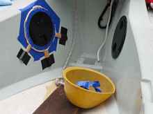
| Figure 3. The two forward hatchplates before
and after trimming epoxy squeeze-out. The newly enlarged holes
for the new hatchplates were a bit oversize. Before applying
epoxy, I added more masking to the GRP, masked the hatchplate
flanges to protect them and taped short pieces of wood to
the side tanks to more accurately position the flanges. |
 |
I had applied release agents to the hatchplate flanges, intending
to remove and re-seat them in silicon sealer against the epoxy.
For release agents, I used extra strong hair spray followed by
soapy shaving gel, then wiped clean. However, the hatch plate
flanges were stuck in place. I am guessing that the shaving gel
removed the hair spray allowing the epoxy to bond with the flange.
In the overall process, I discovered two useful tips. First, gelled
alcohol hand sanitizer works almost as well as acetone in removing
unset resin and hardener. It is also safer and a lot easier to
use. Next, the warning about keeping acetone from the Sea Dog™
hatchplates is apt. I cleaned a small amount of epoxy from a hatch
plate with a shop towel only slightly damp with acetone. The towel
was immediately smudged.
*****

|