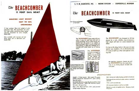
| I’m guessing
that the year is just after WWII either in the late
40’s or early 50’s when my boat was created
by L.V.M. Associates Inc. of Coopersville, Michigan.
The hull is of molded polystyrene foam, 11 feet overall
and weighs 27 pounds. It has a protective paint coating
and has a beam of 36 inches.
It came in two models
depending on the sail chosen. Model 600 was of red
“heavy guage (06mil) polyethylene heat sealed
construction. Model 700 was red and white striped
Translene (nylon). Both had a sail area of 60 sqft.
The mast was 7’
and the boom and yard were 10’ long extruded
high temper Aliminum (The mast step allowed for a
pole of just 1.125” inches in diameter,while
the rudder and centerboard were of varnished plywood.
Along the centerline
and 3” forward of the stern was a 6” aluminum
tube that had an inside diameter of 0.5” with
a steel washer crimped on top and bottom and served
as the rudder shaft tube. My quess is that originally
the Tiller had a steel threaded rod bolted to it,
to act as a pivot point and protruded far enough astern
so as to allow the rudder to be attached to it. Please
remember that this was before the word fiberglass
was invented or Kool Cigarettes were offering a “Snark”
for 2,000 coupons.
So much for the specifications
listed in the sales flyer.
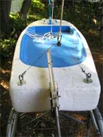
Three years ago, my
then 12 year old grandson pulled the hull out of the
garbage of a distant neighbor on “Bulk Pickup
Day” and dragged it a ½ mile home where
it remained until this summer. All it had was the
centerboard, now painted blue and in the bow and stern
threaded steel rods corroded solid to their aluminum
sleeves.
About six weeks ago
I searched the internet to find something that looked
like this hull and found a brochure (two sides of
a single sheet) of what appears to be a duplicate
of this boat. Since that time I haven’t been
able to find that original site, but at least I have
the pictures and the specs to go by, in restoring
this hull to sailing condition.
Where to start? For
me it was the internet and while searching I surfed
into Duckworks and its links. I gained knowledge and
soon had in mind how my restoration would come about.
First, how do I restore
a 60 year old Styrofoam hull full of holes and gouges
especially around where I removed the steel shafts.
(Steel and aluminum don’t mix in a salt water
marine atmosphere.) My solution was to use a product
that my wife had purchased to eliminate drafts through
our exterior walls. It is called “Great Stuff”
and is a product of the Dow Chemical Co. It is a foam
sealant for cracks and gaps and ends up just like
Styrofoam. It was worth a try as it is also a bonding
agent to most materials. My only fear was that it
might dissolve the existing Styrofoam, it didn’t.
Soon the entire hull was pockmarked with expanded
bubbles of foam and one hour later with a fine tooth
hacksaw blade the boat was back to being at a uniform
surface level. What I discovered is that this too
is foam with thousands of tiny bubbles that end up
looking like the surface of the moon. Using an orbital
sander the boat’s surface was as good as I
could get it in the absence of a suitable substance
like “spackle” or “bondo”
substance might do for a sheetrock wall or a car’s
exterior body.
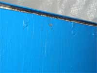
Next came two coats
of latex paint that did a good job if filling in some
of the small craters. Be aware that blue masking tape
is good only on smooth flat surfaces, I had to do
touchup all along where the blue met the white paint.
In the meantime the
search for aluminum poles started and while many Internet
sites including Ham antenna companies and fencing
companies also had them the cost of shipping anything
over 8’ by freight exceeded the cost of the
material. The answer was to find a local dealer to
avoid shipping costs, but that search was a dead end
also. On the way home from a fencing company, I stopped
at a pool supply company and found that for $23 apiece
I could buy a nested aluminum pole whose outer diameter
was perfect for my mast, and was 8’ long with
no alteration. The inner pole was 1” in diameter
and was also 8’ long so that the maximum length
was 16’. I only needed a boom that was 11’
and a yard that was 13’ but more important the
inner pole did not lock with a twist action, but rather
locked at the top of the outer pole with a compression
fitting. This meant that the inner tube could be locked
at any length and in any position you set it.
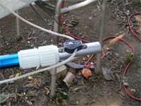
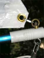
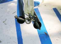
Being a lateen rigged
boat the boom and the yard are both not parallel to
the water but instead these two poles meet at a point
forward of the mast. I decided that the easiest way
to join these two poles was by means of stainless
steel eyebolts with an aluminum spacer tube with rounded
ends to exactly fit the inner diameter of the outer
tube so that the tube wall would not collapse when
the nylon stop nuts were tightened.
 |
click
images to enalarge
|
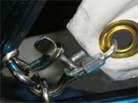
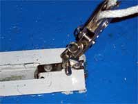
You will note in the
above picture that while I could have interlocked
the two eyebolts but I preferred to join the two with
a shackle that would allow me to tie the Tack of the
sail to this junction.
Next I realized that
since I had an adjustable pole inside the outer pole
of the boom and yard, no fitting could be mounted
that went through these poles such as the hoist point
on the Yard, the gooseneck fitting at the junction
of the mast and boom, or the blocks used for guiding
the mainsheet along the boom.
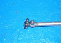
I therefore designed
all these fittings so that they clamped around the
pole with junkbox parts. These clamps also have the
advantage of being able to slide the fittings fore
or aft to find the ideal location for each one.
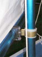
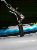
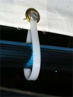
This is my gooseneck
fitting using a clamp fitting around the boom with
a clevis pin through a backup plate and going into
a piece of 2” brass tubing (not pipe) shaped
as shown with a section of a nylon or PVC pipe fitting
used as a bushing. The clevis pin is held to the brass
pipe with a SS cotter pin. The white line seen is
the mast halyard. When the yard is lowered the gooseneck
is thus free to slide down the mast.
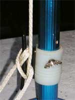
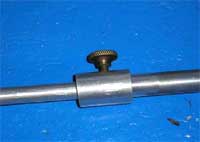
The above view is a
closeup of the halyard cleat that is mounted to another
piece of 1.25” of PVC pipe fitting. The area
just behind the cleat was sanded flat so that the
base of the cleat could mount to a flat surface. Flathead
bolts start inside the pipe with the nuts on the top
of the cleat instead of the other way around. To do
this I had to rout the countersunk holes in the cleat
flat for the nuts and lockwashers. The wingnut shown
locks a bolt that anchors the fitting in place, but
is easily removed so that the gooseneck fitting above
may be slid off the mast.
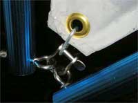
The above photo shows
my masthead fitting and a closeup of the clamping
device, where the two white sections tighten to clamp
this section of aluminum that is only 12” long.
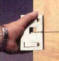
Have you ever wondered
how to tighten the nylon locknut inside the tube when
an ordinary open end wrench, a box wrench or a socket
wrench either could not fit in or lie flat on the
tubes curved inner surface? To solve this problem
I took a piece of half inch steel conduit and with
a metal cutoff saw blade I cut a slot the width of
the nut. Now I was able to hold the nut in place while
I used the screwdriver on the outside.
While the mast is
in view, let me discuss what I did to modify it. In
the above photo I used a 12” tube at the masthead
in place of the regular 8’ inner tube. What
you don’t see is that I reinforced the 8’
mast with two 5’ hardwood spade replacement
handles that were spliced together and cut to the
remaining length of the mast (7’) These handles
were exactly the proper diameter and were held in
place by the bolt holding the halyard cleat. Now there
is no flex in
my mast.
This photo shows the
halyard fitting attached to the padeye that is clamped
to the Yard pole. Being clamped to the pole allows
me to relocate it so that I can find the ideal mounting
point while the inner tube is free to move.
Throughout this picture/story
you will see that I have used 1/8” “Quicklinks.”
Especially through the grommet at the Tack, Clew and
Head of my sail Its elongated shape allows the sail’s
grommet to be attached to the pole end eyebolts, and
may easily be removed. The size of the Quicklink used
is determined by the maximum opening between ends.
In a couple of cases I found that I had to grind a
few threads off the bare end in order to allow a slightly
thicker object
to be inserted.
So far I’ve
discussed the spars and it fittings, now we move to
the styrofoam hull. Unlike any other marine hull material,
one cannot mount anything to it with screws or glue,
so how do you mount the needed fittings?
In my opening paragraphs
I mentioned that the hull had two threaded rods corroded
to an aluminum bushing that had steel washers crimped
to each end of the tube. These bushings were molded
into the hull so that a shaft could be extended through
them.
 |
|
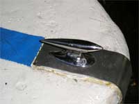
In the bow, I assumed
that they had a cleat installed. In any case I found
a 2.5” wide by 1/8” depression. In this
depression I mounted a piece of stainless steel that
wrapped around the nose of the boat to a point 2”
beyond the shaft holes. Finding a small bow cleat
in my boat supply box I determined that I had to drill
and tap a 5/16” hole in its base. Then I drilled
two 5/16” holes in the ss bow plate directly
below the cleat and the plate on the bottom. Using
two flat head screws I mounted the cleat in the normal
fashion to the top of the bow plate with the tapped
hole in the cleat directly over the holes in the bowplate.
Within the shaft hole I inserted a new spacer tube
the length of which was slightly less than the hull’s
thickness. Using a stainless steel eyebolt with a
shaft long enough to go through the bottom of the
plate the spacer tube, the top plate hole and finally
tightened into the chock’s threaded hole. Thus
the bow now has a towing ring on the hull’s
bottom and a chrome cleat on the forward deck.
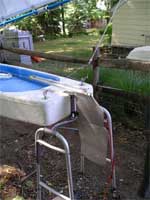
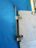
In the stern we needed
a replacement rudder and tiller and a similar stainless
steel mounting bracket had to be fashioned to hold
an aluminum rudder and tiller as seen in the following
photo
In the photo (Left)
above I show the stainless steel mounting plate that
was bent in my shop using my vise as a bending brake.
The aluminum kickup rudder is the gray object on the
right. A stainless steel shaft goes through the entire
object holding the rudder to the mounting plate. The
second screw up from the bottom locks in a piece of
neoprene rubber that is ½” thick with
a hole the diameter of the shaft. This prevents the
shaft from coming loose under any condition even when
turned turtle. The tiller being directly above this
shaft also prevents this pin from coming out unless
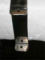
the tiller is raised past vertical. The bolt shown
in the photo below secures the mounting bracket on
top and below. It goes through the original shaft
hole.
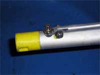
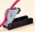
The bar on top is the
tiller is an aluminum extendable tiller extension
as seen below.
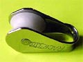
The extension mounts
to the tiller by means of a simple key holder that
divides in two to hold your car keys on one ring and
your other keys on another ring. The lower right photo
shows the clamping device to adjust the length of
the extension handle.
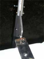
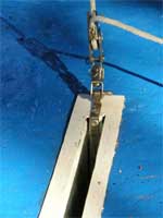
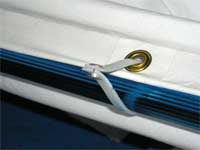
The next item mounted
in the stern is the main sheet traveler as shown in
the next photo.
This simple device
allows the end of the main sheet to be clear of the
tiller, yet allows the boom to swing if you change
tacks. The block used has a steel sheave and the two
eyebolts have ¼”brass rods going through
the hull and secured with similar large washers and
nuts.
The last items are
in the center of the hull. – The centerboard
and the main sheet block.
In this photo (above) we see the centerboard baseplate
and the sheet block assembly. Originally this plate
was made of wood, but I’m not sure how it was
secured. My plates were made of stiff but thin sheet
aluminum By using a thin kerf blade I preserved the
center section without cutting the ends, so that by
cutting this 5/8” wide piece of metal in two
I created two legs that were bent down against the
bow and stern walls of the centerboard shaft. Thus
the bottom plate and the deck plate were mated together
with pop rivets inside the shaft.
Next I had determined that the best place for handling
the main sheet was in the center and not in the stern,
so I had to find a way to clamp the sheet in that
location. With the centerboard plates secured to each
other, I had a secure location to mount the main sheet
block.
This block was in my parts box and was perfect as
it had a V cleat built into it, but mounting the block
required that I create out of a strip of stainless
steel a special pad eye.
As seen above this padeye was poprivited not only
on top but also within the shaft wall also.
Next, problem was the centerboard and how to prevent
it from falling through the shaft. What I did was
to saw a 1.25’ deep cut along its top edge centerline,
and inserted a piece of aluminum T–Bar.
Using wood screws through the aluminum (pre-drilled)
from both sides the T-bar was locked into place. A
small padeye securing a brass ring. It allows the
raising of the board safely and with the ring lying
flat prevents toe injury.
The item saved for last was the sail.
The first thing I did before any restoration took
place was to search the internet. That was how I was
able to find the flyer about the boat and the size
and type of sail it came with. I learned that cloth
sails sold for as much as $500, and that was beyond
my means. This led me to Polytarp and Polysail and
then to Polytarp companies where I learned about the
weave the mil thickness UV protection, the cost and
the difference between the tarp size and the actual
dimension edge to edge that can vary as much as 9”
shorter.
I decided that while a sail kit might come with
more detailed instructions, I was going to build the
oldest sail in the world that is still being used.
The Lateen Sail.
The flyer said that my boat originally had a 7’
mast and 10’ boom and yard with a total sail
area of 60 sqft. With my purchased spars having a
capacity of 16’ long, I could in theory build
a lateen sail of 128 sqft. But that would be overpowering.
I searched the internet for building a lateen sail
such as the Sunfish, the Sailfish and the Funfish
as well as 9 other boats and compiled a list that
had the dimensions of the Luff, Foot, Leech and total
area. By simply adjusting the length of my poles and
the toppinglift length as a temporary substitute for
the leech, I could make any of the sails on my list.
I chose to make a sail that had a luff of 13’
and a foot of 11’ for an area of 61.48 sqft.
My reasoning being that the length of the boat was
11’ and a boom length of 11’. Therefore
the Clew would not overhang the stern if the Tack
was at the bow. All my fittings were adjustable so
I have the ability of moving the Tack to the stern
by as much as 2.5 feet and the same with the Yard,
thus giving me more or less headroom below the boom.
I followed the instructions of Dave Gray of Polysail
Int. and laid out my 14’ square white tarp that
cost less than $15, on my asphalt driveway (why do
we park on a driveway and drive on a parkway?) In
any case, I used cut-nails in the corner grommets
and stretched the tarp as tight as possible, yet the
fold line creases remained. These creases were to
haunt me later on.
Removing the spars from the boat (actually just the
boom and the yard which were adjusted to the proper
lengths required along with the rope representing
the leech length) they were laid down on the tarp
and positioned to allow my adding a curve to the foot
and luff.
My instructions said that 1/3rd the distance from
the tack should be the maximum dimension of the curve.
For the Foot it was 2” and on the luff it was
3.5 inches.
Using a dry marker pen (removable ink) I marked
the tarp along the outside of the tubing and the rope
(leech) and then removed the spars. In each corner
I drew two 6x6 squares of extra material that was
to be used for re-enforcing the corners.
Locating the maximum curve points I laid the corner
of a brick on those points and by using a 25’
x 1” tape measure on edge, I was able to layout
a perfect curve along the luff and foot. Again I used
the dry marker and marked the curve on the tarp, while
at the same time removing the original lines with
a damp rag.
With the help of my grandson, we now applied carpet
tape along the inside of my remaining lines, and tried
to make sure I had 100% adhesion. This was where the
fold marks in the tarp came into play as the tape
was not flat where it passed over the folds. With
a scissor I had to cut the tape so that the cut ends
would overlap each other and thus be flat.
Now with a sharp scissor we followed the outside
edge of the carpet tape and the two boxes of extra
material in each corner and cut out the sail and removed
the excess material.
So far the sail looked good with the curves on the
Foot and Luff. I now removed the protective paper
from the second side of the carpet tape and laid 1/8”
Dacron bolt rope on the inside edge of the carpet
tape starting and ending at the Tack where I left
an extra 12” of line. ¼ inch line would
have been overkill and using Nylon would have been
wrong as it stretches.
The next operation was the most difficult. I had
to fold the inside edge of the carpet tape over the
bolt rope and seal down the carpet tape without wrinkles.
Doing this and following the curve with the bolt rope
stretched and in the exact position was near impossible
to accomplish perfectly. By the way, I mention bolt
rope, do you know the only other rope on a sailboat?
The rest are all called lines. The one other exception
is called the Bell rope and is attached to the clapper
of the ships bell to make ringing easier. We all knew
that- right?
The next step was locating where to place the grommets
and starting at the Tack I marked every 18”
along the Foot and Luff and wrapped a 2’ wide
by 4” piece of vinyl tape around the edge of
the sail for added reinforcement. I didn’t but
most at this point should wrap the edges of the sail
in vinyl tape for a more finished look.
The next step was to finish and reinforce the corners
with the extra material held down with carpet tape
and with the end of the sail folded in so that the
corner grommet would be close to the bolt rope that
curves around at this point The corner is then finished
with vinyl tape leaving no exposed polytarp.
The last step was to install the grommets and here
I used ½” brass grommets in the corners
and 3/8” ones in-between.
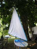
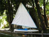
As you see in the last two photos above, the Tack,
Clew, and Head were anchored to the spars with 1/8”
“Quicklinks” going to eyebolts with the
adjustable pole now used to stretch the sail tight.
My final idea was how to secure the sail to the
spars and still allow the sail to travel toward the
tack when I collapsed the boom and yard down to 8’
for travel and storage. My solution may be seen in
the final photos below.
 |
|
Normally there are a couple of ways to secure the
sail to spars. We often see line laced around the
spar and through the grommets using one long line
or by using individual lines or electric cable ties.
I used cable ties but different from the designed
method. I went to Home Depot and purchased a package
of extra heavy 24” cable ties of nylon that
are 1/16” thick by 3/8” wide. I cut off
the head and cut the remainder into three equal strips.
I then drilled a 3/16” hole in the center about
½” in from each end and inserted what
is called aluminum “Post nuts” These are
items obtained in stationery stores for binding various
thickness reports into binders. Shown in the photo
are posts that are ¼” long, but they
are available in many size lengths and fit the standard
three hole paper. The left photo shows the normal
mounting position.
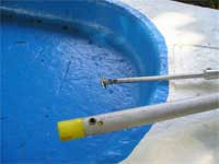
There remains but two tasks to complete the project.
One is to add a nameplate to the stern and the second
is to launch the craft and see if it sinks or sails.
Wish me a fair wind at my back, as I have never sailed
in a centerboard boat. My total sailing experience
has been in sail canoes with leeboards and keel sailboats
in sizes from 16’ up to 52’.
I sincerely hope that this article will inspire
others and give them ideas that they can emulate.
I wish to thank all who have posted to the internet
and those who posted on the “dwforum”
for their aid and knowledge.

Feedback:
In the article, Robert Goldwyn guesses that his Beachcomber sailboat is from the 1940s or 1950s. According to his papers, Lawrence Valentine Meyer (L.V.M. Associates), was building boats from 1960-1963 at his Michigan Fiberglass Company plant in Holland and then Borculo, which made Super Porpoise sailboats and Lake 'n Sea runabouts. He was employed by another firm from 1942-1959 making reinforced plastic products, but not boats. I remember his son, Lawrence Valentine Meyering, Jr., telling me that his family had moved to Coopersville after the boat plant was lost.
Thanks!
Geoffrey Reynolds
Director
Joint Archives of Holland
Hope College
P.O. Box 9000
Holland, MI 49422-9000
|