
 Custom Search
|
| boat plans |
| canoe/kayak |
| electrical |
| epoxy/supplies |
| fasteners |
| gear |
| gift certificates |
| hardware |
| hatches/deckplates |
| media |
| paint/varnish |
| rope/line |
| rowing/sculling |
| sailmaking |
| sails |
| tools |

| join |
| home |
| indexes |
| classifieds |
| calendar |
| archives |
| about |
| links |
| Join Duckworks Get free newsletter CLICK HERE |
|
|
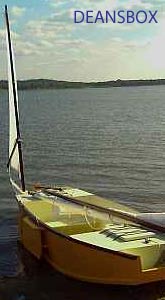
| Kathleen, The Third Chapter - Part 2 |
by Dan Rogers - Diamond Lake, Washington - USA |
Parts 1- 2 - 3 - 4 - 5 - 6 - 7 - 8 - 9 - 10 - 11 - 12 - 13 - 14 Getting just a bit ahead of ourselves, can be a good thing for the soul. But, how we do the current step is based a lot on how we’re gonna’ do the next step. So, it should all work out. There’s this voice that I almost never hear, at the Frankenwerk morning staff meetings. Let’s call that voice, the one of reason. Anyhow, he piped up today and laid the whole complexity thing bare. All he said, was, “Just use the foam cutter you borrowed from Sam to make the tooling, TO MAKE THE TOOLING…” then he went back to doodling on his placemat. Kate’s gonna’ be some kinda;’ upset when she sees what he did to that placemat. But, all of a sudden, we’ve got a real good picture of how to get this curved and tapered and rounded and cambered top together. “Make the tooling to make the tooling,” he said. Wow. Brilliant. Of course, like with every far-flung operation, the rest of the assemblage had to offer their opinions, observations, and of course, cautions. The Yeahbutt’s were the first to point out the basic fly in this particular ointment. The first tool is always the hardest part for this particular band saw operator. Seems, I almost always miss the mark and have to shape things with a belt sander and serendipity. But, Mr. Reason piped up again, and simply put the whole outfit to shame, with, “Soooooo, go slow, be careful, and don’t be afraid to do it over if you don’t like it…” What a guy, huh? So, the meeting went on for a while. But, this is what we’ve got so far. The lid will need to run for about 9-10 feet fore and aft. It will need a “pleasing” amount of camber. It needs to be about 6 feet across at the rear, and down to about 4-1/2 feet at the nose. The nose and rear roundings should complement each other. The nose rounding is still waiting on a rather vigorous discussion between the future operator and the Style Department. It would look a lot better to have a center post in the windshield, with a “pleasing” angle between the sections, that meet the deck in a “pleasing” curve. The ops guy insists that he’d just as soon not have to look past that centerpost while standing his helm watches. I did point out that the ’49 Chevys had center posts to deal with the then-paucity of curved glass in the automotive world. But, I also had to agree that the ‘53s with their no-post windshields were a lot easier to look out of. That discussion goes on, and on. The real geewhizz moment comes when you visualize how this whole thing can - and should - come together. First off, I’ll have to build a strong back to work on. Probably on the floor, to allow for getting to the centerline easy. There is a job for a tick-stick to locate the 3-demensional perimeter. Mr. JW calls ‘em something else, like “tiddly winks” er’ somethin’, like that. Anyhow, the tick stick will then relocate the “pleasing” curvature from the foundation arc to the cabin lid.
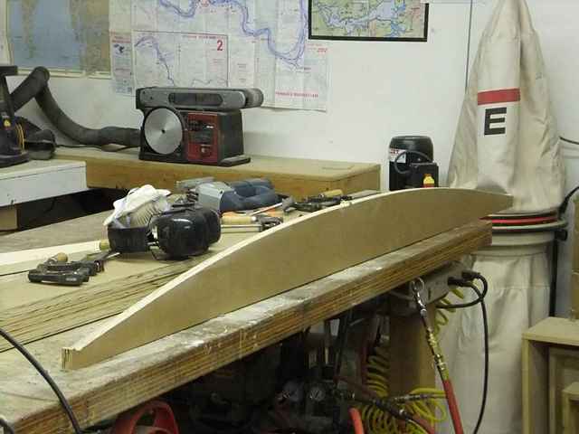
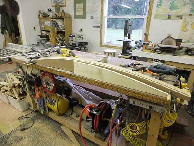
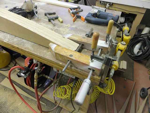
Then, I’ll have to go slow and careful, and make a PAIR or curved forms in plywood that will make the cutting guides for 2” foam-on-edge forms to be cut with Sam’s genius wire setup. When I have “enough” of these forms; the concave side will be mounted on the strong back with the perimeter set up with the tick-stick, from the tick-board, now set in exactly the same point in space on the strong back that it started out on the boat. Sort of an “in loco parentis” thing, if I ever heard of one. But, the foam cutting boys insist that it’s just a piece-of-cake. Unlike last time. I hope!
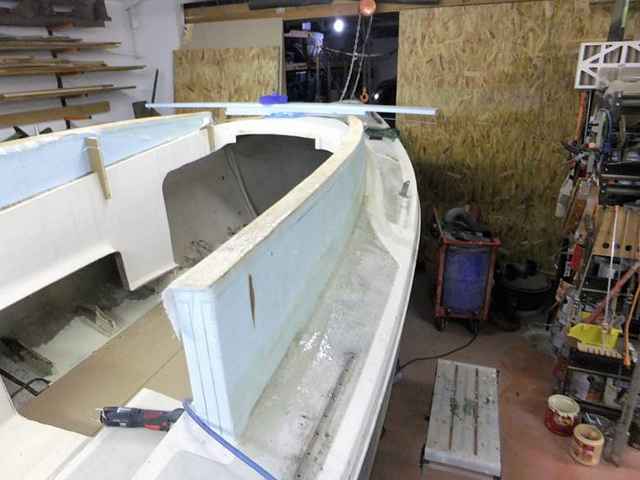
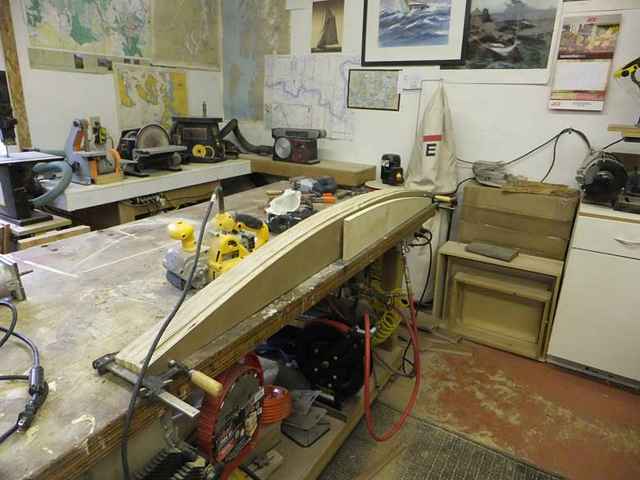
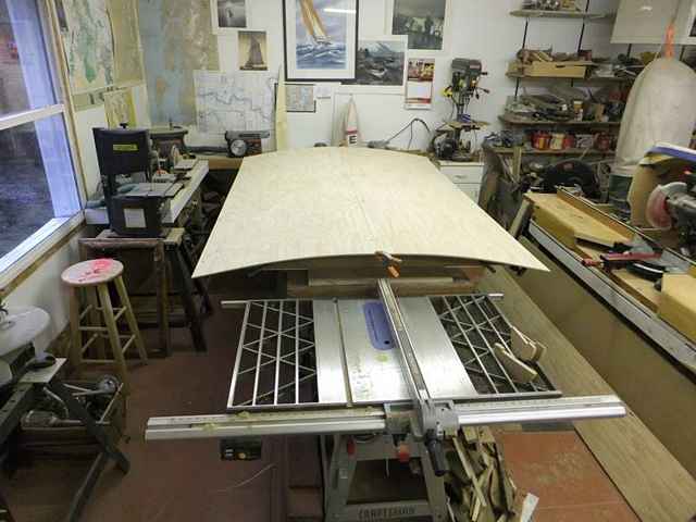
Each of these internal forms had to stay with the top last time, and truth-be-told, they were all a little different from each other and different end-to-end. Like to drive me crazy!
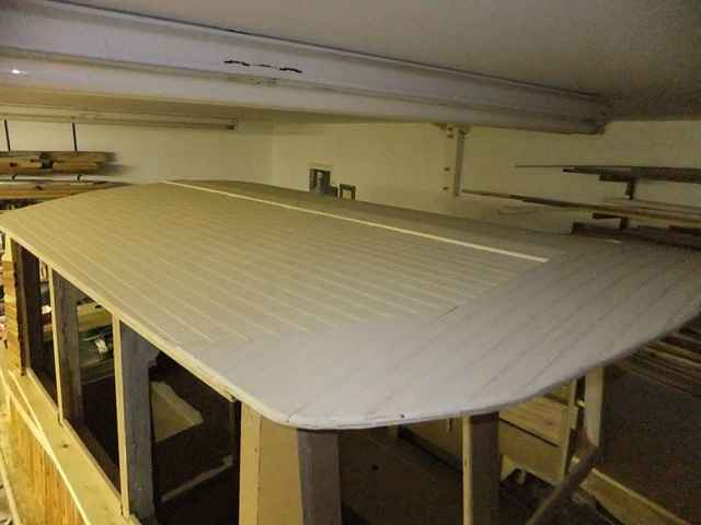
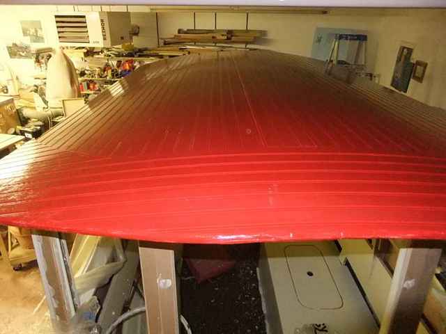
This is sort of how I did it last time. Too heavy, and not quite the right amount of “pleasing curvature.” It did turn out OK. Just not quite good enough.
Once the convex forms are set up to a “pleasing” arrangement; I’ll have to convince a collection of styro coffee cups all squished into a 1” sheet to lay down and stay put in the form(s). Next in, should be a layer of 1/8” ply that should - SHOULD - stay glued and sort of even-out the gonna’ be lower side of this thing. It should also hold a bunch of styro sheet pieces together, as it’s real hard to get a 6 x 10 out of a 4 x 8 without some serious prestidigitation. Then, thin, bullnosed cedar strips will glue down to the ply (door skin) interface. And, this brings us rapidly to the next genius-discovery. The “waste” side of the form tool, to be made outa’ 2-inch foam becomes the presser-squisher-former thingie(s). This is to hopefully allow for not having a nailing point for the strips. Just a glue-and-squish model. Then, depending upon how much spring-back we get; the whole shebang gets flipped over and either: (a) glassed over with the latest (safe to put on your Cheerieo’s) Duckypoxy, (b) armoured with multiple layers of the really-heavy kraft paper that I just happen to have a gigantic roll of, or (c) plywood and paint on the top. All, while still - HOPEFULLY - still in the strongback/building form. I really do hope Mr. Reason continues to show up at the planning sessions. With him around, things just seem a whole lot more reasonable. KnowhatImean? |
To comment on Duckworks articles, please visit one of the following:
|


 |