|
|
| Building
Annie - A Navigator 15ft Yawl - Pt 1 |
| By Robert Ditterich - Geelong,
Victoria - Australia
|
 |
| To
Part One
To
Part Two
To Part Three
A Pictorial Essay of a Navigator
Build
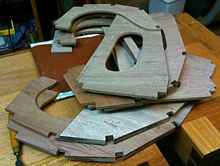 |
The cockpit bulkheads are formed from the seat
base, with a 9mm plywood arm overlapping it to form the stringer
supports and the seat backs and side deck supports. Because
the bulkheads are drawn at 1:5 scale and in two overlapping
parts, I found it helpful to loft full sized sections to check
measurements and enable accurate assembly. |
 |
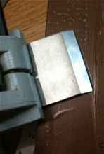
Here the 20mm doubler has been glued (oversize
to allow for fairing the hull into the transom) onto the 6mm
transom. |
 |
20mm doublers added oversized, to allow for
the flair of the stringers as they come away from the transom.
|
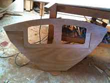 |
This bulkhead has double hatches to go either
side of the mast. The workshop floor has gone back to bomb-site
status after just a few bulkheads. |
 |
B2 having blocks attached to increase the gluing
area behind the stringers- which are very curved at this point.
|
|
Because John has given bulkhead details as dimensioned
1:5 drawings, I found it helpful to loft the full sized outlines
onto paper. This was particularly useful in fitting the two
part cockpit bulkheads, enabling accuracy in fitting them
together. |
 |
Trying out a good Polyurethane glue to reduce
the amount of exposure to epoxy. It foams a little when going
off, filling voids. You can see it around the edges. |
 |
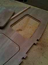
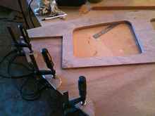
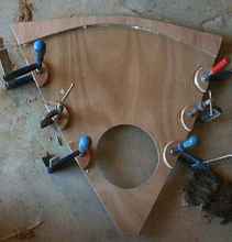
Allowed myself the luxury of cutting the inspection
hatch holes freehand this time, knowing that they'll be covered
by the molding.
Here the symmetry and widths are being tested with a full
width batten before the glue sets. |
|
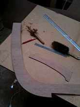
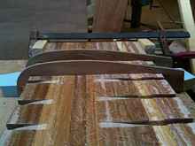
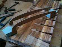
The two outer laminations have been roughly
cut using the more finished centre strip as a template. The
little piece of ply laying there will become a template to
make the centreboard later. It is a half male template at
the top and a half female template at the bottom. |
 |
Using the main stem piece as a template to shape
the 2 doublers. A pattern routing bit (with a bearing) is
used. |
|
Never underestimate the potential of a spokeshave.
My old friend in the background lies ready to help when machines
are too clumsy. |
 |
Rather than using a template to rout the whole
shape, I used the template to cut regular profiles across
both sides of the board, and then used power and hand planes
to take the surface down to the bottom of the profiles; less
noise. The router is kept at a constant distance from the
board, in the shape of the foil section, by moving over the
'bars'. |
 |
The shape was developed from a full sized section
template, and the height was projected at many perpendicular
points to the surface, and at a height sufficient to clear
the bit at maximum depth |
|
2 full sheets of 9mm ply are scarfed together
for joining. The garboard (bottom) panel will be drawn... |
|
John's design for hatch covers seems very good,
but I couldn't bear to waste the cut outs from the hatch holes.
Cut them neatly with a thin blade and it saves the work of
making new infills. I have backed the holes with some thin
ply. |
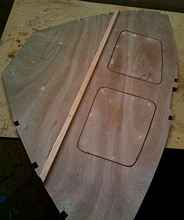 |
These will help make a large volume of reserve
buoyancy forward of the mast, while also allowing the stowage
of gear. |
|
This stringer becomes the support for the cockpit
seat front panel, but also has the role of placing and supporting
many of the bulkheads during assembly. |
 |
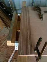
The keelson is 100 x 20. The dimension is cleverly
incorporated into the CB design, so make it accurate. |
|
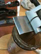
Because this had a chip on the edge from striking
a submerged screw in the previous boat build, I've used a
coarse carborundum water stone to cut back the secondary bevel,
removing the damage. This could have been done with a grinder,
but for such a lovely blade, I prefer to grind by hand, with
grit and water. |
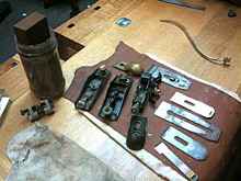 |
Several nice jobs grouped together help concentrate
the mind onto the joys of sharpening. |
|
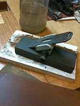
Coarse carborundum stone used to remove chip
on the secondary bevel. I will produce a straight, grey flat
area which will become shinier as finer stones are used. |
|
1200 Japanese water stone and honing guide removing
the scratches from the bevel caused by the coarse stone used
previously |
|
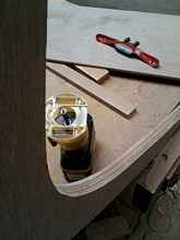
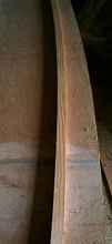
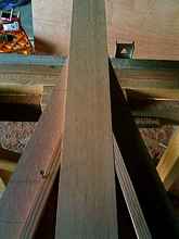
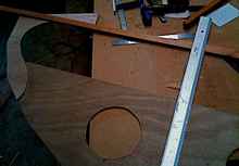
Despite the camera distortion, that centre board
(keelson) has parallel sides. This shot is in just because
I liked the shapes and colours. |
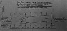 |
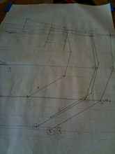
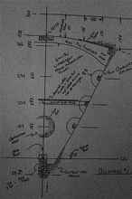
I include this because it illustrates
the designer's method for creating 'x-y' co-ordinates for
locating a fair curve on a grid. It works very well indeed,
but because the horizontal axis starts with a value of 157
instead of 0, a builder using the edge of the ply to mark
out the panel would waste almost enough to make the second
panel. Expensive stuff, marine ply! I recommend either reducing
all the relevant numbers by 157, or locate the ply on a backing
board in such a way as to allow the bottom curve to start
near the edge. |
|
At bottom left, the slot for the stem is nominated
and shown as 10mm, with 20 x 20 packers each side. The stem
diagram, by contrast shows the stem width to be 27mm at this
position. I chose to believe the stem diagram rather than
this one. Note also that on another diagram the king plank
width is shown wider for the yawl rig. |
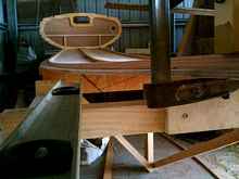 |
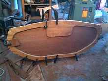
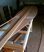
If the rebates that you cut in the bottom of
the transom are snug and accurate, the transom will stand
up by itself and reassure you that your careful placement
of the stringers and keelson will have been worth the care
and effort. |
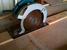 |
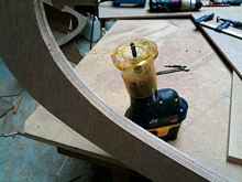
The old heavyweight is used to plunge cut along
the 2 lines. The ends are cut carefully with a jigsaw, because
there is framework under there and a blade hitting it end-on
can give you a scare. Plunge cutting is worth practising on
scrap if it intimidates you. A circular saw gives a much straighter
cut than a jig saw can. |

|
|
|
  |