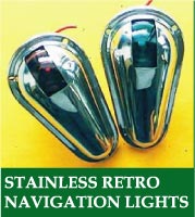
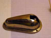
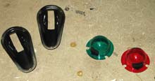
On the AF4B Extreme Makeover I used the stylish “retro side lights”, inexpensively available from Duckworks. In the process I discovered that these lights demand a surface parallel to the boat’s centerline. This necessitated some rather clunky wedges.
I didn’t really like how they looked, and that got me thinking. Maybe these lights could get modified to change the angles. Then we could eliminate or minimize the wedges. So I unscrewed the light and brought them inside for a little mad scientist work.
I measured some Michalak study plans to get an idea of a useful range, and here’s what I found:
Design & Location |
Approx. Wedge Angle |
AF4 at bow |
25 degrees |
Electron front cabin side |
22 degrees |
Frolic2 at bow |
20 degrees |
AF4 front cabin side |
18 degrees |
Frolic2 front cabin side |
16 degrees |
But to apply this knowledge we need to make a test jig.
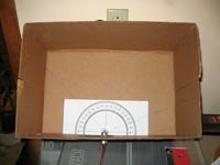
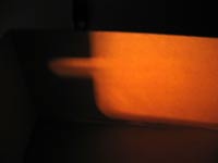
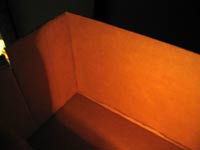
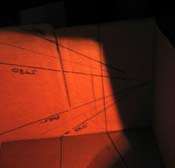
Test Jig
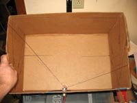
Not much to it, is there? This is just a cardboard box with the light mounted on it, and markings on the sides to denote where the light should cut off. With the desired locations marked, we change the aperture until the light cuts off at the lines.
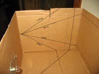
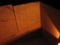
To figure this out, I print a large protractor on office paper. Legally, we want each bow light to cover an arc from dead ahead (maybe 1 degree to the opposite side) and 22.5 degrees abaft the beam (112.5 degrees from dead ahead). To these angles we add the angle of the hull side at the mounting point. In my case this is 22 degrees, so I mark at 22 and 134.5 (20+112.5) degrees.
Remember that the opening on the light is not right at the side of the box. The baseline from which the angle is measured is defined by the distance between the front of the light’s opening and the cardboard – 1 cm in this case. This is not such a big deal once it’s on the boat, but distances are pretty short inside a box, so it is best to account for it. Be sure to use a square, and to first check the box itself for square.
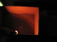
By the way, I did the actual test with fine pen lines. I had to enhance the lines in the photos to make them visible. This is also the case in some of the photos of the nav light shells. Photographing chrome is not at all easy.
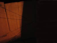
That takes care of the horizontal dimension, but what of the vertical? The only part of the law we are likely to be able to measure without scientific equipment is the 25 degree rule. To paraphrase, at least 50% of the required intensity shall be maintained at all angles within 25 degrees of horizontal. Here’s why it’s easy to measure – if you notice it being a bit dimmer, it is probably half the intensity or less. This is because our eyes perceive light on a logarithmic scale. So we need to look for essentially full brightness to 25 degrees above and below. So again we mark our box accordingly. If we have enough coverage, we can ignore hull flare. But if things get close we might need to take it into account. So we offset these 25 degree angles by the hull’s flare angle, in both directions.
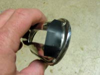
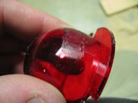
So let’s dig in. (Let me apologize here for the quality of the photos. Low light and chrome are both ugly to photograph and this article has both!)
You can see that it does a pretty good job if it is parallel to the centerline. But that isn’t what we want.
Rear angle
First let’s look at the rear part of the aperture. We will need to cut some metal. Not all at once, though, since tiny amounts of metal change the angle markedly. First let’s extend the aperture lines on the light’s cover. This is so we don’t cut away any metal we want to keep.
Now we start cutting a slot in the middle of those lines to find the right depth. Here’s my first cut.
Not far enough. So we trim a tiny bit at a time until it looks like this.
Then we cut to this depth along the lines we drew earlier, and carefully remove the waste with a square cut. A hacksaw blade works, but a Dremel with a cutoff wheel is a lot easier. You will probably need a triangular file to clean up the corners in either case.
With some angles there will be a gap between the lens and the shell at the rear. I don’t think this is a problem as long as there is a way for water to drain out if it gets in. So it is OK to put sealant between the base plate and the hull, but make sure you don’t put any sealant between the shell and the base plate. If the gap really bothers you, you could always glue clear plastic to the inside of the shell to seal it. I didn’t bother, since the lens it meant to be the waterproof part. I did, however, spray paint the inside of the shell flat black, just in case light tries to bounce around where it shouldn’t be because of the gap.
However, a gap between the lens and shell also narrows the vertical angle. Be sure to check that it falls within the legal parameters. If not, you might need to widen the aperture on the top or bottom.
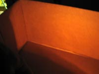
See how it just barely covers the required range? It won’t once hull flare is added. So I trimmed a little more at the top of the aft part of the aperture. When tapered into the rest of the aperture it doesn’t look lopsided because none of these lines are straight anyway.
That should do it. Or maybe not…
An error
How many of you noticed my error above? I used the angle from Electron’s cabin side instead of AF4’s! So I used my protractors to redraw the lines correctly. Now the light will go a few degrees too far astern. Since we need to block out some of the light going forward, we’ll fix that with the same method.
Forward angle
Now let’s first get rid of the overlap at the bow. It misses the line by a lot.
A piece of duct tape marks where we want to cut it off.
I thought I was going to make this permanent by gluing in a piece of stainless steel shim stock. But it is extremely difficult to bend any sheet metal to smoothly match the compound curve of these shells. Instead I painted the mask directly on the lens. Be sure to rough up the plastic a little so the paint will stick. I used gloss black acrylic model paint. Make sure your paint is water-based, since some solvents dissolve acrylic.
I painted the outside of the lens, trusting the paint to stand up to the weather. Some might wish to paint the inside to keep the paint protected, but this would expose it directly to the lamp’s heat. I’m not sure which would pose the greater problem, but recoating seems easier with the exterior method.
Note that I used the same treatment to fix my error at the aft edge. I also painted the inside of the shells with some flat black to minimize stray reflections.
Putting it together
The angles are now correct. The edge of the light is angled from the vertical line to account for hull flare.
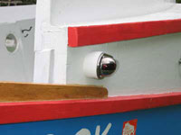
Now the light can mount flat on the hull and look like it was meant to.
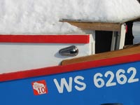 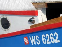
Now that looks more like it!
LEDs
Now I should mention something about power consumption here. Incandescent lights go through batteries pretty fast. I think it is probably only practical to use them if you have an outboard motor that also generates electricity. If your lights are running solely on batteries, I think you need LED nav lights.
The main trouble with converting lights to LED power is getting them aimed correctly. Fortunately, you can do this using the box jig shown above. Better yet, with careful positioning you probably wouldn’t need to mess with cutting the shells or painting the lenses.
But someone else can publish on that, since now I’m working on how to use one set of Duckworks portable LED nav lights on all of my boats.
Rob Rohde-Szudy
Madison, Wisconsin, USA
robrohdeszudy@yahoo.com
Click Here for a List of Articles and Columns by Rob Rohde-Szudy |