I guess I’m the sort of person who can’t leave well enough alone. Maybe that’s a personality flaw and maybe not. I guess you can be the judge after reading this “case study”.
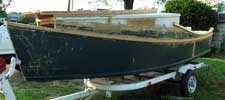
When I got my AF4B from Eric Larson, it was a blank canvas, so to speak. He’d done a fine job of building the hull, but it had received little use. It might seem strange to build a boat then not use it much, but there’s a reason. He built AF4B for the Lower Wisconsin River, which is near me. He’s near Lake Michigan, which requires a whole different kind of boat. Driving 125 miles to the intended water equates to a boat that sees little use. (Take careful note if you’re considering a design for water that is not very near you!) Now Eric is restoring a lovely 1960 lapstrake runabout, which will do him some good on the big lake.
Although this AF4B is “done”, anyone who has ever built a boat knows that the real project begins after you get it in the water. So picking up where Eric left off, I used the boat a few times and learned a few things. As is often the case with me, it snowballed into a big project. Let’s start at the top…literally.
Slot Tops and Bow Boarding
I think designer Jim Michalak originally drew this boat to have a nearly full length slot top, and for good reason. Jim is entirely right when he comments on the convenience of being able to easily walk forward and over the bow to dry land. Eric for some reason preferred a smaller opening, and left about 20” of deck in front of the slot before the bulkhead. This makes docking by the bow rather clumsy, and some degree of athleticism is needed to scramble to the beach. I think I remember Eric being taller than me, so that might be part of it.
The original partial slot also had the ugly side-effect of dividing limited cabin headroom with a big 2x4 frame.
Addressing this problem requires some deck cutting.
New Slot-Top
I would normally have made the slot straight-sided and parallel for the sake of simplicity. But the existing slot was 24” wide, and that was too wide for the forward bulkhead. To do a straight taper of the slot would have run off the edges of the plywood and the forward corners of the existing slot. New plywood for the decks seemed wasteful. So I sprung a curve in the slot frames. This would not work for sliding hatches, but this cover will simply lift off, so it’s OK.
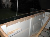
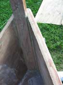
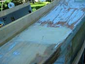
If you have never done this kind of demolition, it can be tricky to get the lumber off and leave the plywood in tact. Basically the idea is to remove the fasteners, then saw off the lumber close to the plywood. Maybe 1/4”. A sharp plane or chisel finishes the removal and a belt sander makes a smooth surface for glue or paint. Actually a belt sander can do the whole thing after sawing, but be careful. You can take layer of plywood off pretty fast with 50 grit.
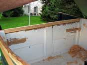
Oddly, Eric had the forward part of the cabin decked in 3/8” plywood, the aft end in 1/4”. I assume this has to do with what is left over after building the lower hull. I replaced the 3/8” with 1/4” to save weight and make it easier to attach the full-length frames. Here it is with the old decking removed.
The new slot frames are a lot smaller and lighter than the old ones because now they won’t ever need to support a person’s weight. I went with 1x3 instead of 1x2 because I bet kids will hang on the rails a lot. But don’t buy 1x3 – get 1x6 and rip it in half. Small lumber is never much good because it is from trees that weren’t capable of making larger lumber.
I also marked the plywood for the new decks in this position. With everything tacked into place with drywall screws, I only needed to trace onto the plywood the lines of the sheer, bulkheads and the slot frame. I didn’t cut right to the lines, though. I left an extra half inch or so and took it off later with a panel cutting bit on a router. Fast and accurate! It’s not too bad with a jigsaw followed by a belt sander either.
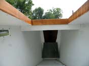
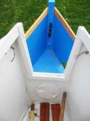
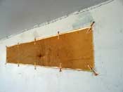
Here are the decks glued into place. This photo is after painting. I swear I took a photo right after doing it, but I guess the camera ate it.
The seams between new plywood and old are joined with typical Instant Boats-type clench-nailed butt straps.
I made a simple slot cover, cutting it overly long, since I wasn’t quite sure of the overhang I would want. Unfortunately it turned out to be a bad sheet of plywood and the top layer delaminated in the first light rain! Odd too, since this was the same stuff I built the Polepunt out of. But at least I could stop worrying about rain while I finished the rest of the mods. We’ll come back to the slot cover in a later article, since it involves a discussion of the fore and aft entries as well.
But this brings us to a bigger change.
Stern Freeboard
Jim is very conservative with freeboard for obvious reasons. But on the first outing with the AF4B, the kids discovered they couldn’t reach the water with their hands. This is a big deal to them and if the kids didn’t like the boat, I would too would soon be getting rid of it. Simply lowering the rail aft looked ridiculous. A few drawings led me to borrow some of the styling of Kilburn Adams’ SkiffAmerica20 design. Here are the lines before and after.
This gives us lower stern freeboard and slightly easier entry over the bow. Maybe a little less weight too. The proportions might not be quite as perfect as one might wish, but I think they are as close as you can get in a 16.5’ boat, especially without moving any bulkheads.
The freeboard is high enough on AF4B that I think this is mostly a cosmetic change. Sort of like when they slap a split grille on a Chevy and call it a Pontiac. But before you get out your saw, I would be very leery of trying this on an AF-series sailboat without having the designer run a few numbers for you. I doubt it would cost you much. My guess is that the width of the cabin slot is more important to self-rescue than the cockpit freeboard, but don’t take my word for it.
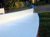
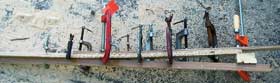
New Wales
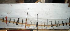
To replace wales, I needed to be able to reach the inside and outside at the same time. So it was handy that I had already built the full-length slot top. In removing the old gunwales, much of the structure would be lost, so I attached the new wales first. This is a simple matter of sanding, glue and screws.
I didn’t bother with any lofting, since the wales themselves serve as battens. From the drawings I measured fore and aft heights, plus the height and distance from stern of the lowest point, and the height at each bulkhead. The natural fairness of the wood takes care of the rest. Here are the dimensions I started with:
I did draw lines on the hull after initial fitting, though, so I could drill pilot holes from the outside of the boat. That way I couldn’t miss the wale. Once the glue cured, I removed the old wales. This is easiest if you cut a lot of kerfs with a circular saw and chisel out the waste. Be sure to cut a LOT of kerfs, though, or the wales’ grain can split right down into the plywood. I had to fill a couple holes because I got lazy with this. The belt sander takes off the last bit, down to clean wood.
 |
|
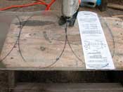
The full-length wales are no real trouble to bend into place, but the tighter bend in the cockpit “coaming” is likely to break cheap construction grade wood. Fortunately I’m a new member of “The Laminati” – the secret society of people using modern glue to make the best of cheap, crappy wood. You could try to laminate this one in place, but I think it is a lot easier flat on a scrap of plywood. (Just kidding about the secret society, by the way…poor people like me never get invited to those things.)
I got the measurements by springing a batten on the hull. Actually, it was one of the .75 x .75” strips I laminated. Take note that I had to do the main wale first, since at least some of the old wale had to be cut away to create a space for the new coaming.
Here are the dimensions I laminated to, measured from the hull. One of the blocks made things unfair and I had to remove it, but either way it will get it close enough to spring into place when the screws are put in.
Aft to Fore in feet |
Vertical in cm |
Transom |
8.6 |
1 |
3.5 |
2 |
0.5 |
3 |
0.2 |
4 |
2.9 |
5 |
7.3 |
6 |
13.4 |
7 |
20.5 |
(Yeah I know I’m mixing metric and US measurements. I’m easing into metric.)
Here is our friend TiteBond III at work. Note the waxed paper keeping the laminates from sticking to the plywood.
I should also mention that some fine, smooth nails are a great help in keeping the strips aligned. Hammering strips into alignment doesn’t usually work. You can clamp them to the laminating board, but this can be pretty slow. I pin them with a finish nail wherever they don’t want to line up. The smarter way is to glue up oversized blanks, then rip and plane them to the final dimension.
These blanks got the usual cleanup with a plane before mounting.
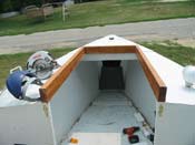
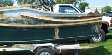
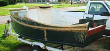
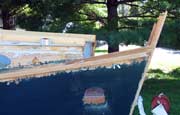
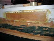
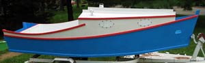
With the new coamings in place, we can cut away the old superstructure.
Finally we start to get a flavor of the new form. Not bad. Time for some rebuilding.
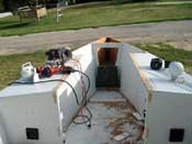
Motor Well Framing
When we cut away the old coamings, some of the motor well framing went with it. Here’s how I added it back.
I had planned to cover the plywood’s end grain with wood cap rails, but rain was on the way. So I had to break down and brush on some epoxy instead. Once that was done, there seemed little point in adding the rails. But if you do something similar with cap rails, be sure to laminate the coamings smaller of they will look too big compared to the wales. This would have been true for me, so it is probably just as well I used the epoxy.
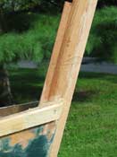
Stempost Extension
I probably should have made the sheer less springy and used only the original stempost, but it just didn’t look right to me. I think the top of the stem needs to be on the line formed by the cabin top, and the apparent deck level is higher now, since the slot top rather than the deck appears to be the top line. So I had to add a piece of false stempost.
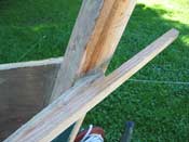
This can be really easy or really hard, depending on the design. Fortunately, on instant boats like the AF4B it is really easy. The stem is a single bevel for its whole length. So we need only figure out the bevel and rip pieces to extend and sandwich the original piece.
You can’t just measure the angle on top of the stem because it is not cut at 90 degrees to the long dimension. So to measure it correctly, we need a bevel gauge and a square. Measure in a few spots, since there might be variation.
Knowing this bevel, we rip a short piece to match the dimensions of the existing stempost, then cut the end bevel to make an extension of the existing stempost. From here on it’s easy. We rip a longer piece to fit the aft face down to the anchor well deck, but this one can be square-sided. Finally, we rip a much longer piece to form a new cutwater. Here they are glued and screwed in place.
I used red oak for the new cutwater in case I mash it against the winch, and red cedar for the rest for light weight. To avoid fasteners showing on the outer stem, I drilled pilot holes from the centerline of the outside of the original stem, then clamped the outer stem in place and finished the holes from inside, taking care not to drill through. This is basically how John Gardner recommends making a stem in Classic Small Craft You Can Build.
The only remaining task on the stempost was to artfully cut the top. Culler regarded this as an art, and did it differently on every boat. I don’t know that I added much to the art form, but I guess it looks OK. But I don’t want to show it to you just yet because this hull form doesn’t quite look right without buffalo rails.
I’m quite sure Jim will disapprove of this mod, since it adds weight for pure vanity. Hopefully I made up for it by removing weight aft, where the weight of crew and motor generally is. On the positive side, however, bow boarding is improved.
Buffalo Rails
I have no idea how these came to be called “buffalo rails”. I’m using Pete Culler’s terminology, since he really seemed to like them, and used them on many of his boats. I made these from scrap oak flooring, but softwood construction lumber would probably be OK too. However hardwood is good for a part that takes the kind of beating this one probably will. Here’s the template in place.
The pain in the butt with using oak is the difficulty in making them take the curve of the side. Again I laminated. Three ¼” layers were not too hard to bend for lamination.
But before laminating I had to figure out how much curvature was needed. This only requires a straightedge and a tape measure. With the straightedge flat against the side of the cabin, measure the distance between the straightedge and the stempost.
Once we know this, we set up a jig. The jig is simple – a block nailed to a 1x2 on edge.
You can see on the left where the top layer ends short of the rest. I wanted this rail to be just a little inside the wale, so I omitted one layer where the rail meets the cabin.
Once laminated, it is a simple matter to cut and plane to the line. The next bit is fitting the buffalo rails to the stempost. I got it fairly close with the “right” way, where you set the new piece parallel to its final position, then draw a line parallel to where you want it to meet the stem. But of course this degenerated into try-and-fit with the belt sander.
Finally, the fasteners. You should definitely dry fit something like this, both in case of error, and so you can do the first varnishing off the hull. First I put two screws into the rail, through the cabin side. Then two through the rail into the stem. Then I added about 4 screws from the underside on each side.
My apologies to Captain Pete’s shade that I couldn’t figure out a good way to use his Nova Scotia bitt, which he often paired with the buffalo rails. Maybe you have to be from Maine to understand the significance of the names of these pieces.
The anchor line runs through the chock cut in the buffalo rail and cleats to the horn and pin of the Nova Scotia bitt. I assume the utility is that you can put a foot on the foredeck rail and really haul on the line. But this bitt requires a foredeck. Instead I mounted a big cleat on the back of the stempost.
Don’t trust screws for something like this. I put in T-nuts and covered them with Bondo.
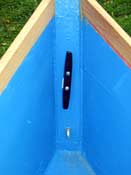
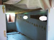
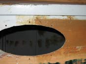
New Portholes
But I’m getting ahead of myself. The old quadrilateral windows looked ridiculous with this new retro look. (I sure wish I’d conceived of this mod before putting them in!) But the old windows went to a good home and are paired with Chris Feller’s AF3, now owned by Shawn Payment in North Carolina. But I still had some holes to fill and new windows to install.
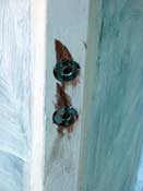
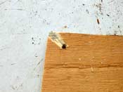
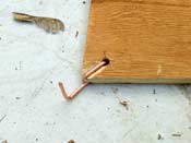
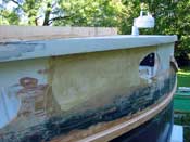
Filling the holes required cutting plywood to fit the gap. I stitched it into place with copper wire pulled out of old scraps of Romex. But I didn’t twist them like in normal stitch and tape. Instead I just made a “staple” so I could hammer the wire down flush with the surface of the plywood. This is a lot easier if you cut channels with a chisel or knife. An angle grinder makes really short work of it.
I’m way too cheap to use much epoxy so far above the waterline, so I ran a bead of PL400 along the gap on the outside. Then I forced it flat with a putty knife, which squeezes some through to the other side.
Fortunately you won’t have to mess with any of this if you build this flavor of AF4 from the beginning.
After curing hard, it’s time to cut holes for new ports. The new ports are four 13 x 6.75” elliptical pieces of 1/8” plexiglass. You might need stronger material for a sailboat, but it is not too likely a powerboat will end up on its side too often.
To generate ellipses, do an internet search for “ellipse generator” and you’ll get some useful hits. I used the very first hit, which was https://www.geek.casaforge.com/code/ellipse2.php. I like the look of an ellipse that is twice as wide as it is tall.
Make a couple templates full sized and draw on the cutout line for the hole and the screwholes. You want about 3/4” overlap of plastic and plywood. Tape the templates on the hull and look at it a lot of times with fresh eyes before cutting anything.
Transfer the lines to the hull by tapping a finish nail through the paper every half inch or so. Then cut along the line with a jigsaw.
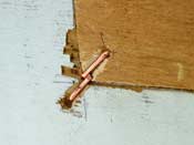
Annoyingly, the portholes overlap the old, plugged hole. But by sheer dumb luck they avoided the butt straps inside the cabin. By even more dumb luck, I didn’t need to add any more “staples” where the new hole intersected the old one. I’d love to say I planned it that way, but…
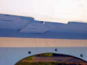
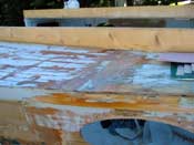
Still, we need some reinforcement for these stitched joints. PL400 is quite weak in shear and the copper staples represent most of the strength. They are probably adequate, but to prevent future cracking along these joints, fiberglass and epoxy is a wise addition. But in the spirit of el-cheapo experimentation, I did the starboard side with epoxy, and the port with PL400, 6 oz fiberglass in both cases.
|
Epoxy |
PL400
|
While I was at it I did the same for the butt joints in the decks.
Epoxy |
PL400
|
Time will tell how the PL400 holds up, but for now I can tell you that it is harder to get smooth. Sanding creates heat and easily makes it gummy. Ideally you get your final smoothing right when you put it on. This takes a wide putty knife, some mineral spirits, and practice. Chief Redelk down in Louisiana reports that it can be done, but he works with these construction adhesives a whole lot. He suggests that Heavy Duty Liquid Nails is better for this kind of thing. I didn’t try it, but PL400 drags badly. However I was able to sand PL400 a bit by taking light cuts alternating by 90 degrees. Even then the adhesion to the substrate has to be perfect or it will just peel off in rolls like rubber cement. I filled these imperfections with latex caulk.
While these experiments are interesting, it is certainly easier to use epoxy and sand smooth, if you can tolerate the cost and shipping. I would not use polyester resin on something like this, since the surface prep has to be perfect to get it to stick reliably. I have yet to see a perfect surface prep with a remodeling project.
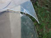
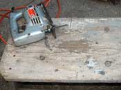
Time to glaze the windows. Cutting acrylic (Plexiglass) is slow, because if you overheat it you get melting rather than cutting, and if the plastic isn’t well supported it will chip. A bandsaw is wonderful but I didn’t want to make a trip out to my dad’s place just to cut some windows. The trouble is that the typical upward-cutting jigsaw blade will break out a chip of plastic and launch it at your face.
Glad I had my face shield on! So I needed a better way to support the plastic next to the blade. I found a downward-cutting blade (small teeth – I think for hardwood) and cut a slot in an old stool. Voila…bandsaw-like function for cheap! This finished the cuts without incident.
Tom Hamernik and I were discussing the problem and he mentioned the idea of mounting the saw’s base to a piece of scrap plywood and making a jigsaw table. This would work with a normal upward-cutting blade. I thought it was a lot easier to get a non-standard blade, but if your hardware store doesn’t carry them, you do have options. Safety warnings should be thoroughly obvious here unless you want your Julius Caesar audition to be extra convincing.
Back on acrylic, drilling presents similar challenges. Too much pressure and it breaks or melts. I bored 1/8” pilot holes, then finished to ¼”. This leaves some space around the #8 machine screws. You don’t want the plastic touching the screws or it will crack at that point. The windows are mounted on a 5/8” overlap and sealed with clear silicone RTV, the final tightening done after the cure. I put the nuts on the outside because I wanted the smoother screw heads inside.
If you wanted to get really fancy, you could make painted plywood frames for the outside, to cover up the caulked overlap. I thought it looked OK without this treatment, and I wasn’t that excited about protecting more end grain. I guess I could have highlighted the overlap by painting it blue before putting the windows in, though. This would have provided a blue “frame” showing through the clear sealant and plexi. But I guess it looks OK without it.
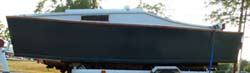
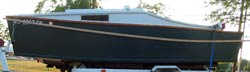
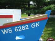
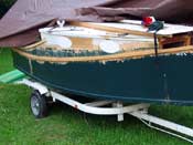
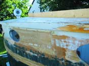
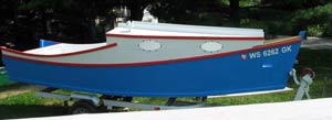
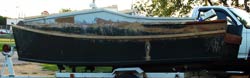
So after all that, here’s the finished hull.
My paint job as some runs, but that’s how it is when little kids are helping. I figure that their memories of helping dad will last a lot longer than any of these boats anyway. My one gripe is that I should have made the wales a little thinner and the coamings quite a bit thinner. Maybe 1.25” for the wales and 1” for the coamings. Less if caprails are used. If I were starting from scratch I’d do the same with the strip that holds the cabin top to the sides, but that is still original in this case. However I would not bother to taper any of these members, though some think that looks really nice. And of course I’d caution about taking too much strength away from a sailboat or a powerboat meant for heavy weather.
In any case, I hope Jim doesn’t think it is too much of a bastardization of his design. Maybe it will gain the interest of people who aren’t into the raised deck look.
Rob Rohde-Szudy
Madison, Wisconsin, USA
robrohdeszudy@yahoo.com
Click Here for a List of Articles and Columns by Rob Rohde-Szudy |