| Motor
Well Slot Cover for the Bolger Light Schooner
…or other boats with similar motor wells
Last time we talked about some of the problems
with the motor well on the Bolger Light Schooner,
and dealt with the pain-in-the-butt slot cover. But
unfortunately, that wasn’t enough for me.
To review, Bolger drew the schooner for a 2hp, 1
cyl motor, which barely fits. Here in “Beerbratistan”
itty-bitty motors are much more expensive than the
5-20 hp models favored by fishermen. So I have a Johnson
5.5, which is every bit as large as a modern 15. This
presented a problem in the schooner, because the motor
couldn’t tilt all the way up. In fact, it couldn’t
even clear the slot until I cut a notch in the motor
well bulkhead.
Obviously, I lose freeboard this way, which is probably
not good. Also annoying was that fitting a noise deflecting
hood would be much trickier, assuming I ever got around
to it. Worst of all was the lack of clearance for
fitting the motor with remote controls. The motor
well decks are flush with the “transom”
that holds the motor. You need a few inches below
the top of that transom for the cables. Otherwise
the cables have nowhere to go when the motor is tilted
up. And you need it clear all the way to the side
of the boat if you want remote steering too.
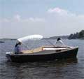
That pushed me over the edge. It was time to rebuild
this thing properly. My idea of “properly”
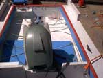
is a Michalak-type slop well forward of the motor.
Here’s one on an AF4B.
This one doesn’t have the air boxes beside
the motor like on the schooner, but the well in front
of the motor provides space for the motor to tilt
up without losing freeboard, and lets the splashed
water and leaked fuel drain easily.
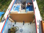
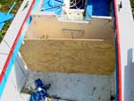
Changes already made
I had already made some changes to the design. I
had widened the motor well from 8” to 9”,
and I’m very pleased with the result. It is
just enough room to get the slot cover in and out.
10” might be better. But 8” surely isn’t
enough for the bigger engine.
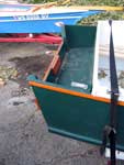
I also decked over the rear “pockets”
next to the motor well. I think everyone does this
to the light schooner. You need the buoyancy back
there if you ever capsize, and you don’t want
pockets for gasoline vapors to collect and explode.
Deck the pockets over and those vapors drop right
out the bottom.
Motor clearance
The first thing to do is figure out how much clearance
the motor needs. Tilted all the way up, the top of
this motor is about 12” forward of the transom
it’s clamped to. The schooner design only allows
7”. I decided to give an extra inch just in
case, so the motor well bulkhead needed to move forward
6”
I was toying with remote steering the motor, so the
other important dimension is how far below the transom
clamp the steering sheaves will wind up. These are
about level with the decks underway, but when the
motor is tilted up, the cables interfere with the
flush decks. So the motor well decks would have to
be cut away by at least a couple inches. Again, I
allowed an extra inch to make things easier.
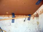
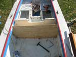
New bulkhead
This part is actually pretty easy. First I marked
a lines roughly 5” and 6” forward of the
old motor well bulkhead. A heat gun and putty knife
removed the bulk of the old paint, and the belt sander
finished up. The object is to obliterate those lines,
since they represent the glue lines. We want nice
fresh wood. It’s pretty hard to get it well-sanded
up under the decks, but get as close as you can. Modern
adhesives will do the rest. When we have bare wood,
we re-mark the line 6” for’d of the bulkhead.
This will be the front face of our new bulkhead.
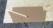
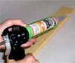
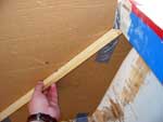
Now we get to do one of those simple procedures with
fancy names – spiling. It’s not a big
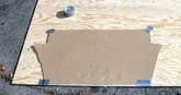
deal at all. Cut a piece of scrap cardboard to fit
the new bulkhead’s plane fairly closely. It
only needs to be close enough that you can tape it
in place.
Then find an oblong scrap of wood and cut a point
at one end. This is your “tick stick”.
An irregular shape is preferred, so it can only fit
one way. Then you put the point in all the corners
you want to mark on the final stock, and simply trace
the shape of the tick stick on the cardboard. Be sure
to get all the points you want the first time, because
you’ll never get that cardboard taped in the
same way.
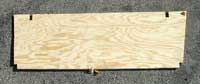
Here’s the cool part. Remove the cardboard
and lay it on your plywood. Now when you match up
the tick stick to the marks on the carboard, you can
trace the point onto the plywood and replicate the
corner points of the final bulkhead.
Then connect the dots. If you are a confident sort
and don’t mind buying more plywood, you can
cut right to the lines. I did. PL400 can fill gaps
to 3/8”. (Mine were smaller, but not small enough
for Titebond III.)
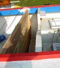
To get it in place I had to cut a bit off the upper
corners and from the hidden part of the slot that
fits around the deck carlins. Because of the boat’s
taper, it still took a hammer to get it into place.
It never would have fit with the framing sticks already
attached, so these have to be added in situ.
Now you have a choice. You could fit this bulkhead
by stitch & tape, which requires no further wood-cutting.
I hate it because it is messy and I’m not good
at it. So I fit this one by nail & glue, just
like the rest of the hull. This means ripping some
frame pieces. Getting the bevels from that piece of
cardboard, we rip some 1x framing sticks. Bolger calls
for 2.5” wide, and that’s what I did,
using a circular saw with a rip fence.
But to make framing we need bevels. Lay a bevel gauge
or divider against each edge to get the bevel. Be
sure the gauge is standing 90 degrees off the cardboard,
or your bevel will come out smaller than it should.
I use a square to make lines on the bulkhead perpendicular
to the edges. Line up one leg of the bevel gauge with
this line and record the bevels. I dry fit all the
parts first, bottom then sides then top.
Not much to it, really.
Trace these angles on the cardboard pattern so you
don’t have to go to the boat and measure for
every cut. Also record the bottom-to-side bevel while
you’re at it.
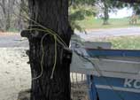
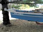
The only real “hard” part of this was
getting the boat partly off the trailer so I could
get screws through the bottom. I untied the boat from
the trailer and tied the light bar to a tree, then
towed the trailer forward, about 4 feet out from under
the boat. Then I tied down the forward end of the
boat, so it wouldn’t fall off the trailer, and
untied from the tree. Afterward, I got the boat back
in place by using the same tree to shove it back on
the trailer.
Back to the bulkhead. After dry fitting everything,
I took it all apart and moved the bulkhead just far
enough to get PL400 in the cracks. Then it’s
a simple matter to glue and re-screw. The hull is
watertight again, even though the project isn’t
done. Could be handy. Of course it’s not as
watertight if you added hatch cover frames like I
did. We’ll get to how that works later.
Next time we’ll start chopping out old stuff.
Rob Rohde-Szudy
Madison, Wisconsin, USA
robrohdeszudy@yahoo.com

Other Articles by Rob Rohde-Szudy:
|