|
A Puzzling Way to Join Plywood |

|
Using Common Woodworking Tools to Join Plywood Panels with an Easy to Make and Assemble Puzzle Joint that Fits with Machine Shop Precision
What is a puzzle joint?
In a puzzle joint, the mating edges of plywood panels are formed with complementary puzzle-like contours. The panel edges often look and fit together like a tabletop jigsaw puzzle. Puzzle joinery allows short panels to be rapidly and easily assembled into longer ones. Puzzle joints are an interesting alternative to scarf joints, butt joints, and fiberglass tape butt joints.
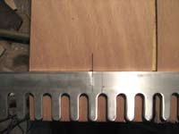
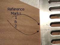
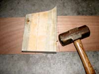
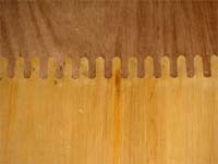 Fig. 1 - This picture shows a puzzle joint made using the techniques described in this article. The joint is not even glued, but you can pick up and move the panel around without affecting the joint. You can even lean it against a wall. See Fig. 2. Fig. 1 - This picture shows a puzzle joint made using the techniques described in this article. The joint is not even glued, but you can pick up and move the panel around without affecting the joint. You can even lean it against a wall. See Fig. 2.
The joint has to be sanded and then taped with fiberglass on both sides to be completed and achieve appropriate strength.
|
|
Puzzle joints have significant advantages. They certainly simplify alignment and clamping concerns when joining panels, even as compared to the butt block approach.
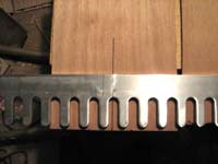
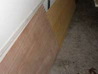 Fig. 2 - Here, the unglued panel of Fig. 1 is leaning against my garage door. No glue. No clamps. No fiberglass yet. The joint is pretty stable anyway. Fig. 2 - Here, the unglued panel of Fig. 1 is leaning against my garage door. No glue. No clamps. No fiberglass yet. The joint is pretty stable anyway.
The joint shown here couples an 8-foot luaun panel to a 4-foot luaun panel. The joint took less than 10 minutes to make and assemble to this stage.
|
|
Puzzle joints are becoming more and more popular among kit manufacturers. The puzzle joints you see in kit boats are machined with high precision using computer controlled cutting tools. And therein lies the dilemma for the home boat builder who builds from scratch. Not many of us have easy or inexpensive access to a computer-controlled router or the like. Quite simply, these joints have been difficult to machine with high precision by home boat builders.
Enter the Taped Finger Joint
The puzzle joints shown in these pictures were made using ordinary woodworking tools that you might already have in your shop. I call the joint a taped finger joint because the puzzle features are in the form of interlocking fingers. The joint is formed with the help of a router, a pattern bit, and a dovetail template.
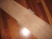 Fig. 3 - Here is another sample of the joinery, this time using scraps of marine plywood. This joint was glued together using Titebond III. This side of the joint is untaped. Fig. 3 - Here is another sample of the joinery, this time using scraps of marine plywood. This joint was glued together using Titebond III. This side of the joint is untaped.
|
|
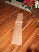 Fig. 4 - Here is the other side of the panel shown in Fig. 3. This side of the joint is taped with 3 layers of roofing fiberglass. Titebond III is used as the “resin”. Fig. 4 - Here is the other side of the panel shown in Fig. 3. This side of the joint is taped with 3 layers of roofing fiberglass. Titebond III is used as the “resin”.
|
|
Like a fiberglass butt joint, this joint when finished will have fiberglass tapes reinforcing the joint on each side. This joint differs, though, in that it has the additional puzzle joint features sandwiched between the tapes. Why go through the trouble of making the puzzle features of this joint if I’m adding fiberglass tape to each side anyway? Isn’t a fiberglass butt splice by itself, without the puzzle joinery, strong enough?
Indeed, it can be. But, the taped finger joint is a keeper anyway. Applying fiberglass tapes to the securely assembled panels is so much easier than applying tapes to panels that are merely butted. No clamps are required. You can even jostle and move the panels around while the resin cures. The panels will not lose their alignment. Because you can move the taped, finger-jointed panels right away, you can move joined assemblies out of the way. This opens up your shop space so you can assemble more panels or perform other work as desired. Try doing this with a taped butt splice in progress. It would be ruined.
 Fig. 5 - This shows the panel of Figs. 3 and 4 being flexed. The panel is flexed so that the taped side of the joint is bowed outward (convex and under tension), while the untaped side (facing me and not visible) is concave under compression. The joint is very strong. Not even a hint of a creak or cracking sound evidencing joint failure. The tape is providing quite a bit of tensile reinforcement to the joint. Fig. 5 - This shows the panel of Figs. 3 and 4 being flexed. The panel is flexed so that the taped side of the joint is bowed outward (convex and under tension), while the untaped side (facing me and not visible) is concave under compression. The joint is very strong. Not even a hint of a creak or cracking sound evidencing joint failure. The tape is providing quite a bit of tensile reinforcement to the joint.
|
|
The finished taped finger joint also offers significant potential to be more robust, especially fully glued versions of the joint. If the tape of a conventional butt splice gets damaged along the butt, the joint can be seriously and immediately compromised. This is not necessarily the case with glued versions of the taped finger joint, where both the tape and glued fingers help hold the joint together.
 Fig. 6 - This shows the panel of Figs. 3 and 4 being flexed. The panel is flexed so that the taped side of the joint is bowed outward (convex and under tension), while the untaped side (facing me and not visible) is concave under compression. The joint is very strong. Not even a hint of a creak or cracking sound evidencing joint failure. The tape is providing quite a bit of tensile reinforcement to the joint. Fig. 6 - This shows the panel of Figs. 3 and 4 being flexed. The panel is flexed so that the taped side of the joint is bowed outward (convex and under tension), while the untaped side (facing me and not visible) is concave under compression. The joint is very strong. Not even a hint of a creak or cracking sound evidencing joint failure. The tape is providing quite a bit of tensile reinforcement to the joint.
|
|
Machining and assembling these features is so simple and fast, that the minimal extra burden of forming the features is more than justified by the overall simplicity and robustness of the joinery as a whole. Try making a traditional fiberglass tape joint and then try making one of these taped joints. When your joints are completed, which approach was simpler and easier overall to you?
How do you make a taped finger joint
for joining plywood panels?
The taped finger joint is made using a router, a pattern trimming bit, and a dovetail template having ½ inch, rounded pins and ½ inch rounded pockets. A few clamps are used to hold the panel and template in place during routing. A mallet and pounding board (block of scrap wood) are used to drive the optionally glued panels together. Whether the joint is pre-glued or not, fiberglass tapes bedded in a suitable resin reinforce each side of the joint.
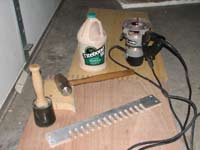 Fig. 7 - These are the tools used to make the joint: a router fitted with a pattern bit, a dovetail template (Porter Cable), a mallet, a block of wood, and some glue. I show a rubber mallet here, but I ended up not using it. Fig. 7 - These are the tools used to make the joint: a router fitted with a pattern bit, a dovetail template (Porter Cable), a mallet, a block of wood, and some glue. I show a rubber mallet here, but I ended up not using it.
|
|
I have to admit, I was not bullish with this approach at first attempt. After machining the first pair of mating panels, I discovered to my chagrin that the pins on one panel appeared to be too wide to fit in the pockets of the other panel. “How could this be?” I pouted. “My template pins and pockets are exactly ½ inch each, and I’m using a good quality pattern bit. These puppies should fit!”
I had initial high hopes for this idea, but those hopes faded at that point in time. I resigned myself to the unscarfable truth that the concept would have to be tossed onto the pile of my other ideas whose implementations fell short of expectations.
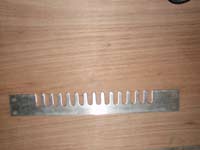 Fig. 8 - This shows the Porter Cable dovetail template a little better. Note how symmetric the dovetail template is. The pins are the same width and length as the adjacent pockets. The symmetry allows the same template to be used to cut the joint features on both mating panels. Fig. 8 - This shows the Porter Cable dovetail template a little better. Note how symmetric the dovetail template is. The pins are the same width and length as the adjacent pockets. The symmetry allows the same template to be used to cut the joint features on both mating panels.
The pins and pockets are both ½ inch wide, matching the ½ inch diameter pattern bit shown in Fig. 9.
|
|
So why did it appear that my pins were too big when in fact it later turned out they were not? The reason has to do with the design of a pattern bit as well as my lack of understanding of how to assemble these joints. It turns out that the bearing on a pattern bit has a slightly larger diameter than the cutting diameter. The difference in diameters is very small. But it means that, when the bearing is flush against the pattern or template, the cutters don’t reach as far. Applied to the dovetail template shown in the picture above, this basically means that the bit is forming narrower pockets and larger pins than you might expect.
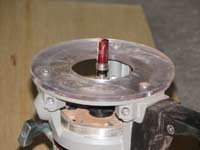 Fig. 9 - This shows the pattern bit a little better. Appreciating that the router here is upside down, the bearing on this bit is at the top of the cutters during use, not the bottom. This is a ½ inch diameter bit with a ¼ inch shank. The router base is transparent so cutting action is viewable. Fig. 9 - This shows the pattern bit a little better. Appreciating that the router here is upside down, the bearing on this bit is at the top of the cutters during use, not the bottom. This is a ½ inch diameter bit with a ¼ inch shank. The router base is transparent so cutting action is viewable.
|
|
Thus, my pins appeared to be too big. Using all my finger and/or thumb pressure, I couldn’t get the parts to fit together. “Aargh,” was my frustrated thought. “It’s back to scarfing.” I put my templates away, and I set the panels aside.
Three weeks passed.
And then I saw a woodworking show in which the host was pounding box joints together with a mallet. A mallet? “Eureka,” I thought. “A mallet.” Pounding the joint together with a mallet could be the key! I went down to my shop, took out those panels, grabbed a mallet, positioned the pins of one panel over the pockets of the other, and then used some tentative taps followed by some moderate whacks to pound the joint together. The parts did fit together after all! And they fit really well!
But, then I discovered that dry fitting the panels before gluing them is not a good idea if subsequent gluing is desired. Once assembled even without glue, the panels can’t be separated without breaking the fingers. So, in less than 10 minutes, I routed another pair, applied glue, and then pounded the new pair together with my mallet. I let the joint cure overnight.
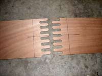
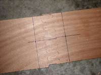
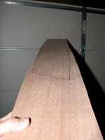 Fig. 10 - Here is another test panel. Two four foot lengths of scrap marine ply are joined using the puzzle joint. No glue and no tapes. I can hold the assembly at one end and the joint is still self-supporting. Try doing this with any other splicing technique moments after the joint is assembled. Fig. 10 - Here is another test panel. Two four foot lengths of scrap marine ply are joined using the puzzle joint. No glue and no tapes. I can hold the assembly at one end and the joint is still self-supporting. Try doing this with any other splicing technique moments after the joint is assembled.
|
|
The next day, I came back and flexed the untaped panel to see how strong the glued joint would be without fiberglass reinforcement. Would the joint be strong as is, or would it need fiberglass reinforcement? Flexing the joint showed that it was strong in compression, but relatively weak in tension. When flexing the panel, the convex side (the side that would typically be on the outside of a hull in most instances) is under tension, while the concave side is under compression. I could get the untaped joint to fail due to tensile failure if I flexed the panel enough. This showed fiberglass tape reinforcement is needed.
I made and assembled another set of panels, but this time applied fiberglass tape to one side of the panel. I used three layers of roofing fiberglass, and my resin was Titebond III, a film-forming waterproof glue. This dried hard enough in a handful of hours so that the cured glue film could not be scratched at all with a fingernail. The fiberglass was tenaciously bonded to the assembled panels, too. In flexing the panel so the tape was on the convex side, I could not get the joint to fail. Instead, the panel failed elsewhere, well away from the taped joint. This showed that when the tensioned side of the joint is reinforced with fiberglass tape, the joint is stronger than the plywood.
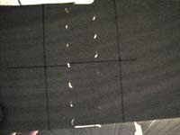 Fig. 11 - The panel of Fig. 10 is being back lit with a light bulb. Those faint white specks you see as a result are gaps in the joint. These are small and easy to fill if desired. But my joints were pretty strong when taped on both sides even if these tiny gaps were not filled. Possibly, the resin used for taping was sucked into and filled these gaps via capillary action in any event. Fig. 11 - The panel of Fig. 10 is being back lit with a light bulb. Those faint white specks you see as a result are gaps in the joint. These are small and easy to fill if desired. But my joints were pretty strong when taped on both sides even if these tiny gaps were not filled. Possibly, the resin used for taping was sucked into and filled these gaps via capillary action in any event.
|
|
But, if I flexed the panel with the tape being on the concave inside, or side of the flexed panel under compression, the untaped, tensioned side of the joint would fail if the panel was flexed moderately. This showed that I would want to tape both sides of the joint for maximum strength. For example, in case of an impact on the joint incorporated into an actual boat hull, even the inside of the curved panel could be momentarily subjected to tensile stresses in a localized area.
The joint when taped on both sides is very, very strong, even without being pre-glued before taping. And this strength is achieved using only a few layers of thin, extremely light roofing fiberglass and Titebond III, not epoxy and more conventional sheathing glass.
The fact that the fully taped joint is strong, even without pre-gluing is expected, since the ordinary fiberglass tape butt joint is reasonably strong when only an ordinary butt joint is sandwiched between the tapes.
Should you pre-glue the fingers before taping the joint? Glue is preferred for at least two reasons. It makes the joint stronger. Plus, using a water-based glue like Titebond III causes the pins to swell a little bit, making a tighter fit.
How do you do this step by step?
The following is one way that you can achieve reasonable registration when you machine and join your panels. To begin with, don’t try to cut out your panel parts into their final shapes before machining them. Join the panels first, and then loft and cut out the desired plank from the already joined panels.
 Step 1. Place a pair of reference marks on the template. I used a very fine tip, water washable marker so my marks could later be removed. Place a first mark on the template that is perpendicular to the back edge of the template and that is roughly is centered on the center pin of the template. Absolute precision is not required, but try to center the mark as close as you can. Then draw another similar reference mark as close to ½ inch away from the first mark as you can get it. Again, absolute precision is not required, but get as close to this as you can. Label one of these #1 and the other #2. Step 1. Place a pair of reference marks on the template. I used a very fine tip, water washable marker so my marks could later be removed. Place a first mark on the template that is perpendicular to the back edge of the template and that is roughly is centered on the center pin of the template. Absolute precision is not required, but try to center the mark as close as you can. Then draw another similar reference mark as close to ½ inch away from the first mark as you can get it. Again, absolute precision is not required, but get as close to this as you can. Label one of these #1 and the other #2.
|
|
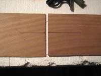 Step 2. Butt your panels against each other and make a linear alignment mark across each panel that is perpendicular to the butted edges and roughly in the center of the butted edges: Step 2. Butt your panels against each other and make a linear alignment mark across each panel that is perpendicular to the butted edges and roughly in the center of the butted edges:
|
|
I’ve used an ink marker here, but use a pencil to make the mark so it will be easy to sand away. The alignment mark will help to initially position the template on each panel. The mark on each panel should be longer than the width of the template so that the template won’t cover the mark completely when later clamped to each panel, respectively.
|
|
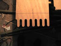
Step 4. Clamp the template to one of the panels so that the back edge of the template is flush with the Step 3 guideline and so that reference guide #1 on the template is aligned with the Step 2 alignment mark. With the template clamped in place, rout the finger joint features. If you need to unclamp and move the template to machine the full edge of the panel, follow the instructions given below to re-position the template. Keep the back edge of the template aligned with the Step 3 guideline as the template is re-positioned. |
 |
|
|
|
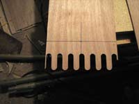
Step 5. Clamp the template to the other panel so that the back edge of the template is flush with the Step 3 guideline and so that alignment guide #2 on the template is aligned with the Step 2 alignment mark of this panel. Using the #2 alignment guide will cause the finger joint pattern to be machined in this panel offset by ½ inch with respect to the fingers on the first panel. The panels should fit together with pretty good registration when you are done. With the template clamped in place, rout the finger joint features. Move clamps one at a time, if needed, to rout as much as you can without moving the template. If you need to unclamp and move the template to machine the full edge of the panel, follow the instructions given in the preceding instruction to re-position the template. |
 |
|
|
|
Step 6. Join the panels. Optionally use glue. If you glue the fingers, let the glue dry before applying the tapes to the joint. |
 |
 |
|
Now you can layout your plank (or other part as appropriate), and cut it out. Since these outside pins tend to fit the worst, note that the layout can be done so that the outboard pins are in a scrap area of your panel. See the plank layout in Fig. 10.
How do you machine a panel that is
wider than the dovetail template?
See the wide panels in Fig. 1. To machine a panel that is wider than the template, you need to move and re-clamp the dovetail along the panel edge. The trick is to re-locate the template with each move so that it is properly registered with already machined features. As one way to do this, you can reposition the template so that at least 3 or 4 fingers of the template directly overlie corresponding fingers already formed in the underlying panel. These already formed panel fingers serve as a registration reference. Your sense of feel using your fingertips very accurately tells you when the template is aligned with these reference features. Clamp the template in place and machine additional features. Repeat as necessary.
I hope you will test the joint and let me know your thoughts. Would you apply the technique to your own boatbuilding?

DW articles about joining plywood sheets:
|