|
design by Warren D. Messer - Seattle, Washington - USA |
Part
1 - Part
2 - Part 3
- Part 4 - Part5
- Part
6
The Laura Bay is the first of a series of multi-chine boats that I will be posting at Duckworks in my section of the Designers Group. The design came about as the result of work I had spent developing a plywood based boat that could compete with the Lazer, and be a whole lot cheaper to build. Download the PDF file, make the model and follow along as I describe the building of the Laura Bay in the coming weeks.
When I was designing the boat I knew that it had to be longer that my Nuthatch pram to get the volume I wanted to carry any kind of load. The hull had started out as a twelve footer, and several rounds of model making resulted in my No. 11 hull which hangs by a string in my kitchen. At twelve feet it was a very graceful hull as it was, but I wanted just a bit more freeboard so I raised it up a bit on the upper hull panel and made the No. 12 hull, which also hangs in my kitchen. While doing a Goggle search on small boats, I came across a discussion board where a very well known Seattle yacht designer was asking for opinions on what was a good hard-shell dingy design. I gave him a call and we talked about dingy designs for a yacht he was designing for a customer. I told him I though I might have something that might interest him. I then took the No. 11 and No. 12 hulls and scaled them back to fit on a 10 foot sheet of plywood (or scarfed pair) and after many, many, many models later, I had four different versions going. I finally settled on a version from the No. 12 family, and model No.6 of that line became the Laura Bay.
This series of boats will be named after women that I should have formed a serious relationship with, but then when we're young we all make wrong choices. Right! I got the most memorable kiss in my life from her and so the Laura Bay is my tribute to that wonderful event.
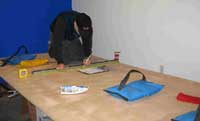
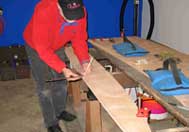
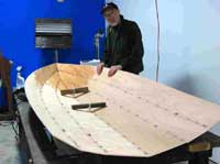
I started construction of this hull without making the larger model that I normally do. The scale models had fit so well, and I was in a bit of a rush to build one of my multi-chine designs, so I threw caution to the wind and forged ahead. I gave my friends at EdenSaw Woods a call to see if they had some 6mm 4x10 in stock and if they might also have some 5x10 too. I found that if I used one 5x10, that I could get the stern panel out of the excess, and not have to buy an extra 4x8. They had the 5x10 and it was only a couple of dollars more than the 4x10 because of a good order they had made. No good deal goes unpunished (but not that bad). I noticed when I got the wood home and placed on my work platform that the long edges didn't match up with the corners squared up and clamped. The other side was off, but with different edges mismatched. I swapped ends and the edges flushed up all round. I stretched a cord along one edge and found that the long side of the plywood was bowed in and the opposite long side was bowed out. Even with the Lloyds stamp in the corner, straight is a relative term in Morocco.
I marked off the one foot gridlines along the edges, but did not run a pencil across the plywood. I wanted to reduce the lines I had to erase. I laid my straight edge on the grid marks and laid the tape measure along side it. I had to measure off the stretched cord as my baseline for the lofting, but things went better than I had feared. I only placed pencil lines on the grids where
a lofting point occurred and that would be covered by fillet material and glass tape.
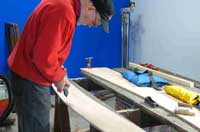
Once the lofting points were established and the 6p nails were tapped in, it was time to break out the twelve foot batten and fair in the curves. This went along as normal as it ever is, with the clamping, light pencil marks, remove it all, look, adjust, replace the nails if a couple of them needed moving and fairing again. Things went very well, with a couple of adjustments on a couple of the lines. One thing to always remember is to hook your tape measure over the end nail and check the edge length of that faired curve/line. Mark these down as you go, and any major difference in matching edge lengths call for a good look to see what is wrong. Since this was a beta first build, I was expecting some wrong numbers to appear. This caused a lot of remeasuring of lofted points and debating as to which point may or may not be off. Once I was happy with what I had and was aware that I needed to be vigilant in the assembly phase; it was time to get out the saw.
I have changed my tune on what type of saw to use and have gone back to using my old Nickolson 26" hand saw with 10 teeth to the inch. The length and height of the blade keep the saw on track and I can get right up to the line and reduce a lot of trimming up time. I found that my pull saw was binding too much and bending the blade. I was going to redo the lofting layout because I was getting more waste between the panels than I wanted using my hand saw, but if you use a circular or jigsaw, you will need the extra room and I will keep it as it is.
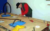
I first cut off the unused part of the 5x10's to make it easier to move the rest of the sheets around on my platform. As you can see, there are gaps that I can saw through and not have to work on the edge. I just slide the clamped panels around as I need to keep from sawing through the platform supports.
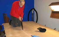
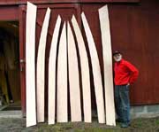
On this boat I marked the stitch wire drill set back lines, beveled the edges on both sides, and drilled only the "upper" edge of the panels, as I cut out each set of panel pairs. Once the panels were all cut out, I separated them in to mirror image sets and pre-shaped them while I worked on the first set of panel pairs.
Only the bottom panel pairs are drilled all round for stitch wires. When drilling, I start with the gridline holes first. That way I know that each pair is matched and I have a common reference point on each side during assembly and a standard reference for fitting the interior. I then drill an inch from the ends and halfway the gridline holes. The drill spacing is reduced to 3" on the first 18-24" at the bow ends.
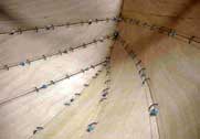
The bottom panels are switched to inside faces touching and the keel edge wired up. I use a medium phillips screwdriver as a gage to tighten to. That is enough extra wire to let the panels open up without pulling through the wood. Once the panels are open, I tie in some cross pieces to hold them in place until the wood takes on a set.
I knew there was a discrepancy in the edge lengths of the first two panels and I went with the gridlines as my match up. This proved to be the correct way, as the bow ends matched up perfectly. I rechecked the plans and adjusted the lower aft corner point of the second panel by ¼" (pretty darn close) and continued with the opposite side.
The third panel's lower edge lengths matched to the 1/8th, so I lined up the stern edges and wired forward. The bow ends matched up again.
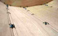
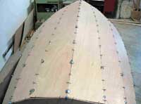
One of the things that I found in stitch in glue construction is that you have to control the butting edges from the get go. If you don't, you can wind up with a boat that has over or under bite edges, and come up short or long on the ends. I discovered halfway through construction of the prototype Nuthatch hull, that I could use ¼" bolts to hold the edges butt to butt. With the Laura Bay having so many panels and so much arc, I had to use lots of them, but it made the construction go very fast. I used around 95 bolts/Nuts and double that with SSA washers. The process was to drill (starting from the stern) the matching wire hole on the bottom of the panel I was working with, (the upper side of the lower panel was already drilled) and put in a loose wire, drill the next 2-3 holes forward and wire them. Go back to the first and tighten it up, making sure to keep it positioned correctly with the stern edge. Drill a ¼" hole near the stern and put in the first bolt and finger tight. Drill a couple more wire holes and twist up the wire, then drill the next ¼" hole one foot ahead of the last one. Go to the stern and tighten the wires and nuts as you work toward the bow. Repeat until you reach the bow. Where four corners come together at the bow, I used a ¼ x 1" bolt with fender washers on both sides to pull it all together.
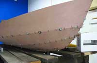
I had an edge length mismatch on the third and fourth panels and adjusted the stern ends back 3/16" and the lower bow corner of the top panel more than I expected (less than ¾ inch). All the changes have been marked up on the master plans and updated. None of the slight errors I found would have hurt the structural soundness of the boat in anyway, but the changes will make your boat easy to build.
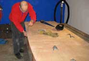
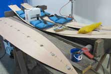
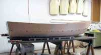
The hull has been squared up (off only ¼"), leveled, spread, and tied down waiting for fillets and tape.
One last teaser photo before the next article.
Warren Messer

|