|
by Tom Beck
170 North Oakland Circle
McDonough, GA 30253
the4becks@peoplepc.com
I have loved to design “gadgets” all my life, so when the boat building hobby bit me, I guess it was only a matter of time until I had to design one of my own. I make my living working on airplanes for a
major airline, so don’t be surprised if some aeronautical sounding terms show up in my plans.
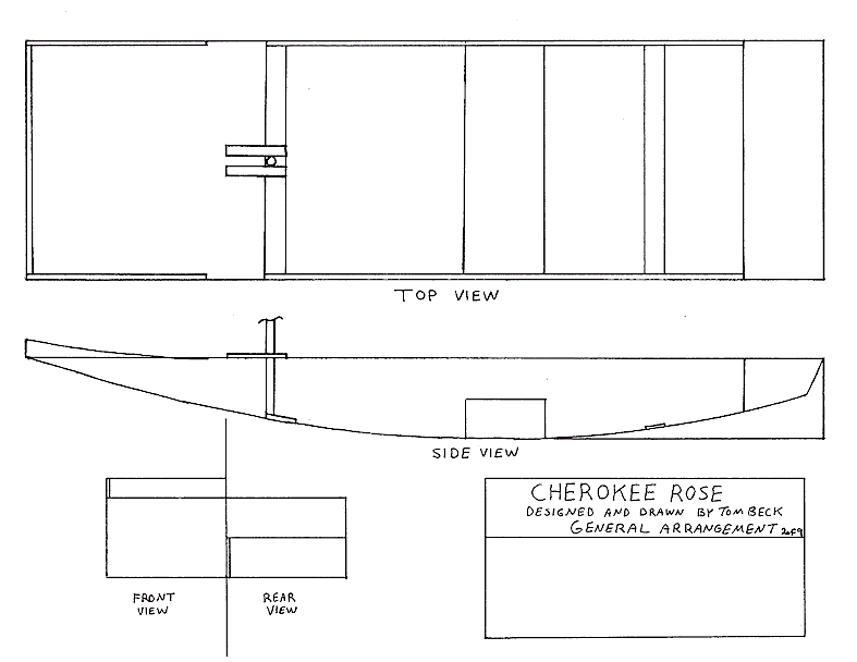
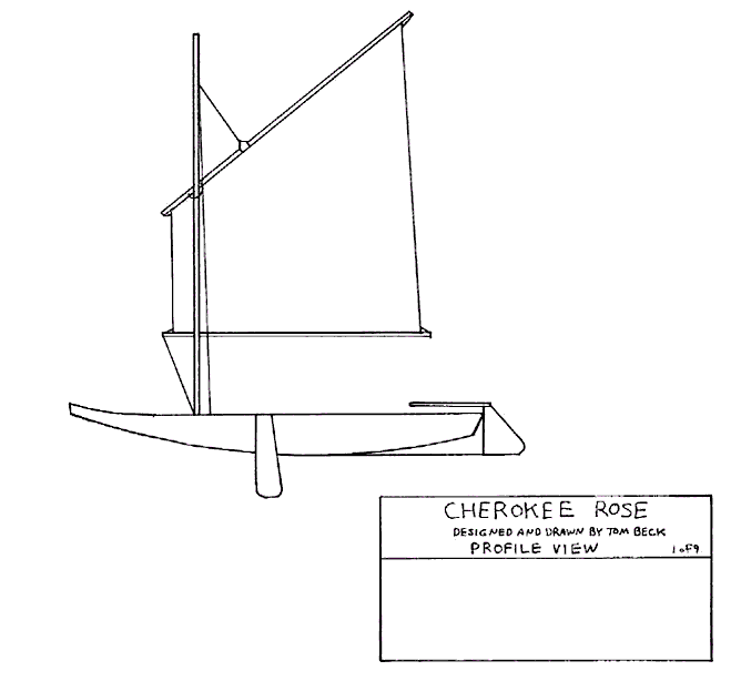
The Cherokee Rose is designed for day sailing on the lakes found in my native state of Georgia. Most of these lakes are man-made. Waves are seldom an issue, but snags and unexpected shallows can be. The flat bottom, leeboards, and rudder/skeg combination make this boat ideal for these lakes. Strong winds are not common here, but generous amounts of flotation are build in just in case it is ever needed.
The original direction of my design was to use every last bit of material in the list of parts. Ultimately, some of the construction was getting ridiculous, and the name U.S.S. Monitor looked like it might fit. I decided to step back, take what I’d learned, pretty it up a bit, and not be quite so concerned about using everything. The result was far more pleasing. I wanted a Southern-sounding name for the boat, but “Magnolia” sounded more like a steamboat on the Mississippi. Since my boat was smaller and prettier (I think, anyway), and designed with the lakes from my
state in mind, I chose the name “Cherokee Rose” after the diminutive wildflower that is Georgia’s state flower.
ASSEMBLY
GENERAL NOTES:
You may have noticed many dimensions seem to be missing from the drawings. If a dimension is missing, the part is intended to be cut to fit. This is intended to allow for variations between actual and nominal sizes, curves, etc. Therefore, adherence to the order of assembly is important.
Whenever possible, ease of nailing was considered; however, in some cases, it may be necessary to have an assistant buck the nail with a heavy object as you drive the nail.
The #17x3/4 copper weatherstrip screws are used (with glue) whenever plywood is attached to anything else, unless otherwise specified.
DISCLAIMER:
This craft is an amateur design. The designer has no control over its manner of construction or over any individual’s manner of operation; therefore, the designer assumes no responsibility for any loss associated with it.
BILL OF MATERIALS
-
2ea. 4’x8’ sheets 1/4” plywood
-
2ea. 10’ 1x12’s
-
2ea. 8’2x4’s
-
2ea. 10’ x 1 1/2” dia. wood poles
-
2ea. 50’lengths of 1/4” nylon rope
-
15’ 3” fiberglass tape
-
1qt. epoxy
-
Small quantity filler (sawdust, microballoons, etc.)
-
300ea. #17x3/4 copper weatherstrip screws
-
20ea. 2” galvanized deck screws
-
1qt. wood glue
-
oarlocks
-
rudder attachment hardware
-
5ea. cleats
-
2ea. 3/8x2 galvanized or stainless bolts
-
4ea. 3/8 galvanized or stainless washers
-
2ea. Galvanized or stainless wing nuts
ASSEMBLY INSTRUCTIONS
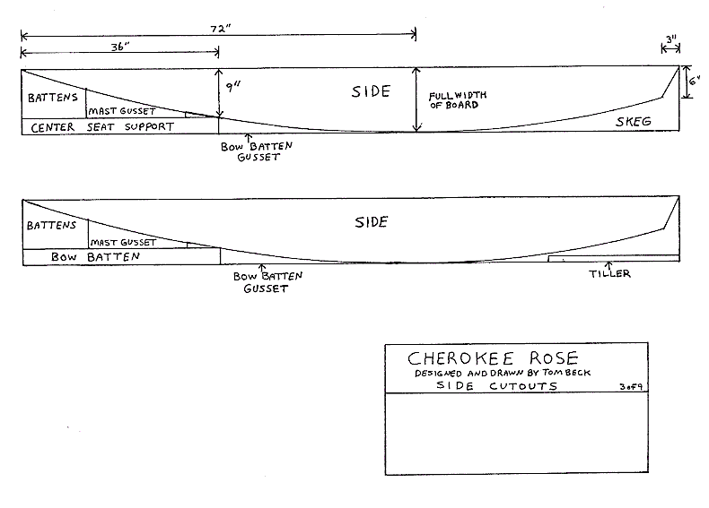
1. Cut out the sides from your 1x12. To do this, make marks at the following locations:
-
0” from the bow end - 0”down
-
36” from the bow end - 9” down
-
72” from the bow end - @ the bottom edge of the board
-
3” from the stern end - 6”down
-
Connect these points using a batten. Use your first side as a template to mark and cut the second side.
-
You can cut the balance of the parts out of the 1x12’s now.
2. Rip all pieces as indicated from both 2x4’s. No dimensions are given - simply measure your boards actual dimensions and divide as shown. Do not cut to length yet.
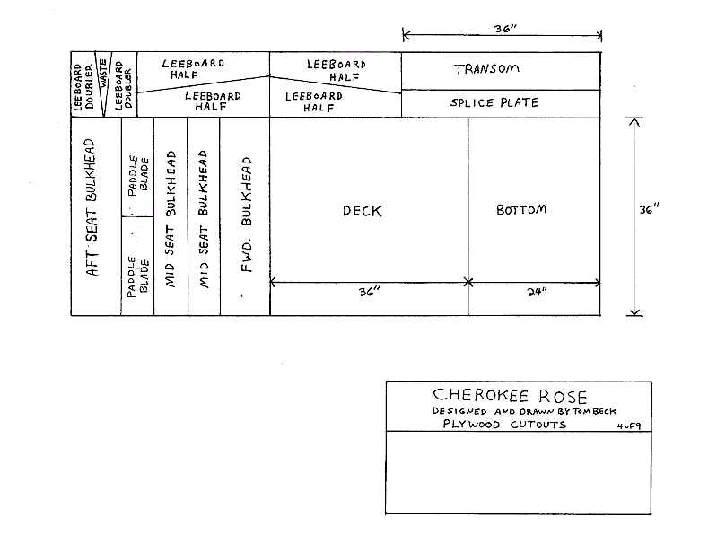
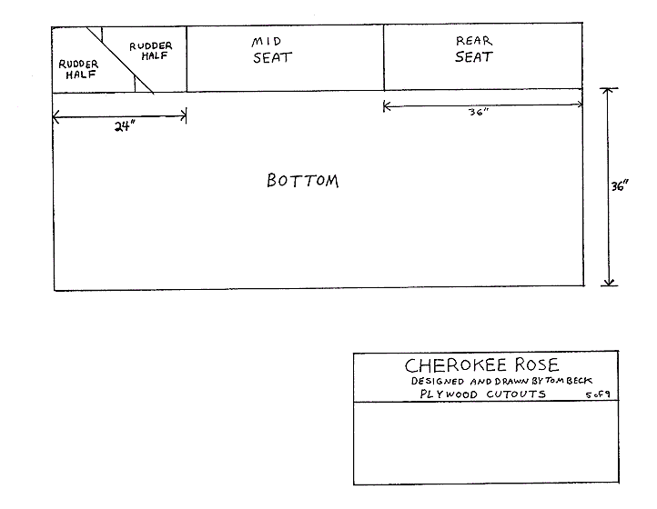
3. Cut the bottom from both pieces of plywood. Cut out the transom/splice plate as a unit.
4. Using the stern end of the side, cut the transom to fit. Subtract the width of the sides and go ahead and install the battens now.
5. Trim the splice plate to clear the sides, and use it to glue the two bottom sections together.
6. With the sides resting upside down on a flat surface, attach the transom to the stern. Make sure the sides are square before nailing!
7. Sand or plane the lower transom batten to eliminate any gaps, and attach the bottom, working from back to front. Leave the excess at the front for now.
8. Cut out the deck and the rear seat. Temporarily tack them in place, and clamp the bow batten in place, also temporarily. Mark where the aft edge of the deck and the forward edge of the aft seat fall and, using a square, draw a line from top to bottom on the inside. Carefully remove the parts.
9. Measure the inside width of the hull at the bottom at the lines you just drew. Now measure the height of the lines. Cut the forward and aft seat bulkheads accordingly.
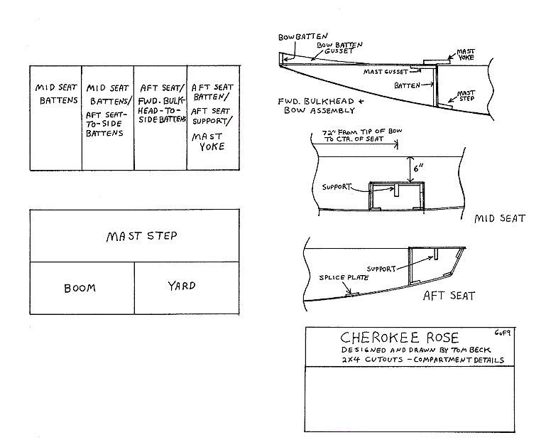
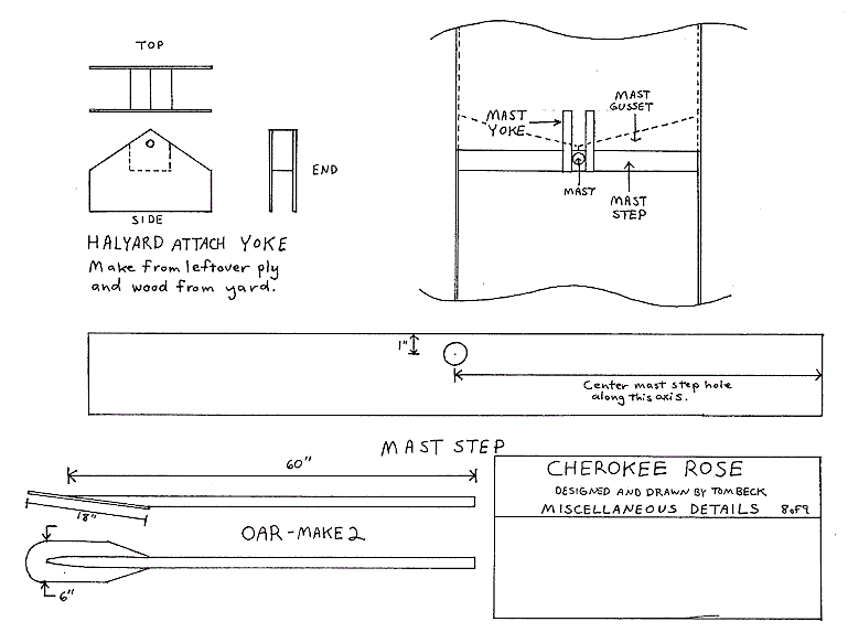
10. Using the forward bulkhead as a guide, Trim the mast support gussets to width, cutting where they meet in the middle. Attach this to the top of the bulkhead and attach the side battens. Do not add a batten at the bottom!
11. Trim the mast step to width and drill the hole for the mast (use a paddle-style bit and only go about 3/4 way through.). Attach the mast step with the front outside edges touching the lines you drew on the sides.
12. Attach the forward bulkhead, making sure it is even with the reference lines and the mast gussets are even with the top.
13. Trim the bow batten to width, and attach the deck, bow batten, and bow batten gussets, Trim/sand off the excess bottom flush with the deck and bow batten.
14. Trim to width a batten for the aft bulkhead where it meets the floor. Add the thickness of the ply you are using aft of the lines you drew, and attach the batten to the bottom, with its front edge even with these points. Attach the battens to the top and sides of the aft seat bulkhead, and fasten the bulkhead in place. It should be flush with the top of the sides. Don’t install the seat.
15. Trim the mid seat to width. Measure a point 72” from the bow and center the seat there (Don’t glue it!). Draw lines on the bottom to locate the fore and aft end of the seat. Unless you are really good, subtract a hair so you can sand the seat to a good fit later. Now, using your square on the top of the sides, draw lines from these marks up the sides, ending 6” from the top edge.
16. Trim the mid seat bulkheads to width, then drop them in place and mark them so they stop 6” from the top of the sides. Attach battens all the way around and install. Don’t install the seat.
17. Find the center point (Going side-to-side) of the splice plate, lower aft seat bulkhead batten, and transom battens. Drill 1/8” holes at these points.
18. Flip the boat over and connect these holes with a line, stopping around the mid seat. Glue and screw the skeg on, making sure it is perpendicular to the bottom. Small gaps are OK. Let the glue dry.
19. Fillet the joint between the skeg and bottom with epoxy and the filler of your choice. While you’re at it, fill any imperfections in the bottom splice and the bottom-to transom joint. Allow to cure, and sand as necessary.
20. Apply 3” fiberglass tape to the skeg-to hull joint, the bottom splice, and the transom-to-bottom joint.
21. Cut the seat supports to width, attach to seats, and install. Secure the seat supports using two deck screws on each end. Be sure measure accurately and drill pilot holes first to avoid creating a split you can’t see. Sand the edges of the seats even.
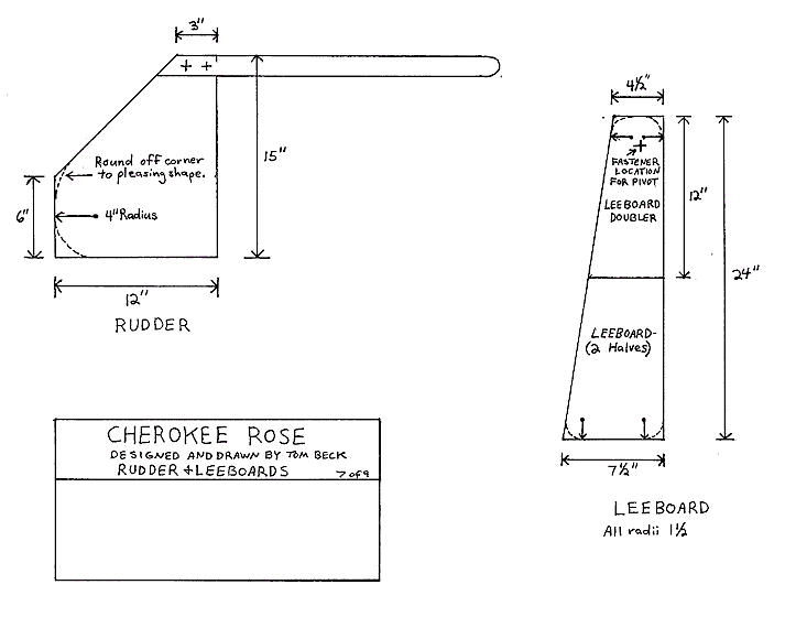
22. Cut out the rudder halves and glue together, pretty side out. When dry, radius the corners and sand all the edged even. Round the aft edges. Attach the tiller with screws.
23. Cut out the leeboard halves and glue together, pretty side out. When dry, glue on leeboard doublers. Radius corners as indicated, and sand edges even and round off.
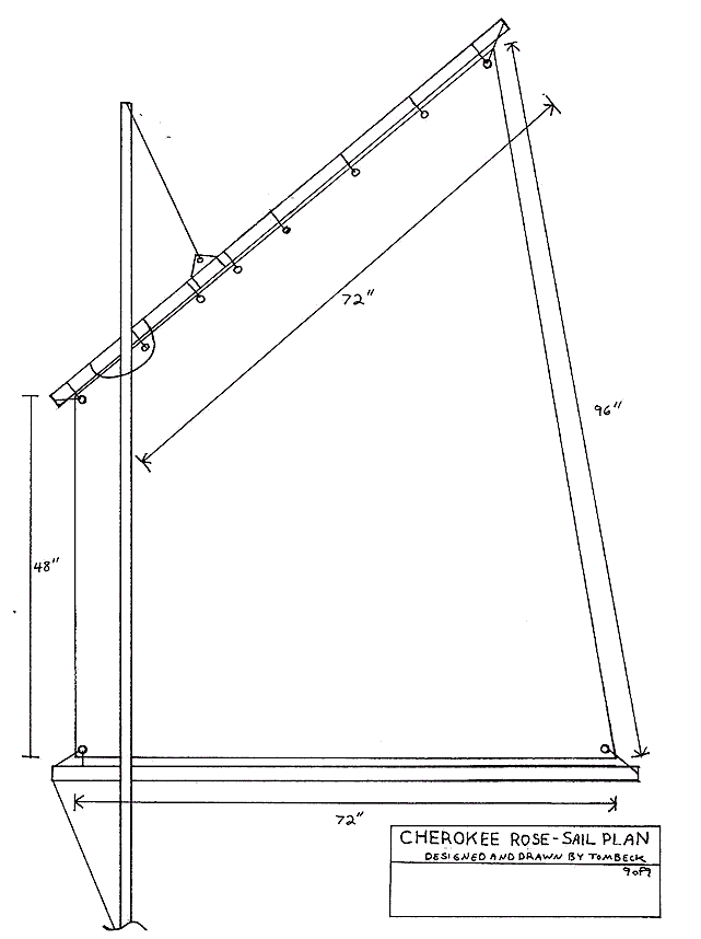
24. Cut yard and boom to length - this means the width of your sail‘s head and foot plus 6“. Notch the end to accept the outhauls.
25. Finish all wood as desired.
26. Cut sail out and reinforce cut edges with duct tape (preferably in the same color as the tarp). Add grommets as shown. Attach to yard and boom. While you’re at it, go ahead and make an extra sail. It will be the first thing to wear out, and when it does, you’ll have another one ready. You may even want to try a different size.
27. Attach rudder.
28. Cut out oar blades. Bevel oar handles and attach blades. Finish.
29. Construct blocks to accept oarlocks out of scrap left over from mast step. Locate these where they suit you.
30. Attach leeboards with c-clamps until you find a location you like. Then drill and attach to the sides with bolts, fender washers, and wing nuts.
31. Rig the sail as shown. Mount a cleat to the mast approximately 6” above the mast yoke, and one cleat on each side of the mast yoke. This allows the mast to be dropped in the step and lashed into place in the yoke. |